ELEKIT TU-8900 or how to build a tube amplifier – part 3
Now we’re moving on to the power board (AC INLET UNIT). The board for the mains voltage used in Europe (230 V) is in a separate bag, along with another board meant for a different voltage – don’t mix them up, they look really similar. You’ll also find 250 V fuses in that same bag.
Heads up – there’s another bag with fuses and fuse holders among the other parts, but the fuses in that one are rated for 125 V. The voltage rating is stamped on the metal end of each fuse – make sure to use the 250 V ones. You can basically toss the 125 V fuses, since they’re not useful in Europe.
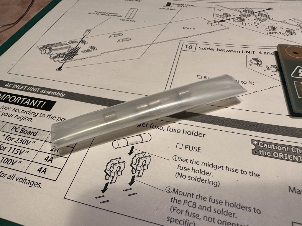
The bag with the fuses
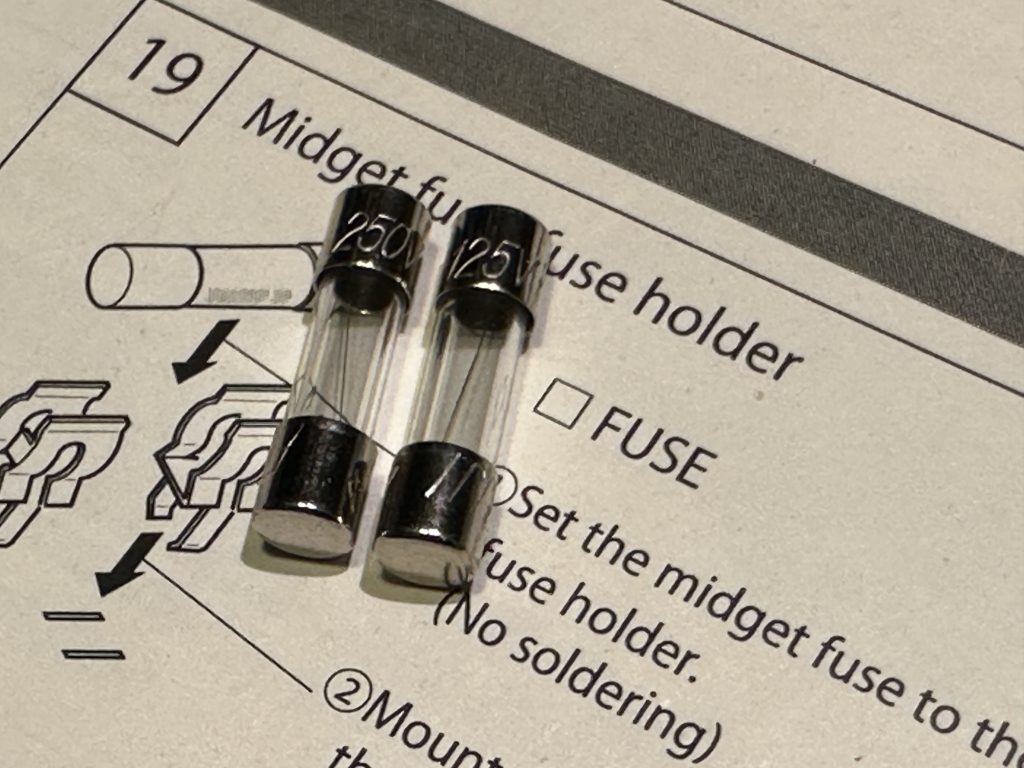
The fuse has the voltage rating stamped on it – on the left side, it says 250 V.
To put it all together, you’ll also need a power switch, a power socket, a socket for connecting the transformer’s output, and a “spark killer” – a component that protects against voltage spikes. It looks kind of like a capacitor, is black, and marked as RE1201.
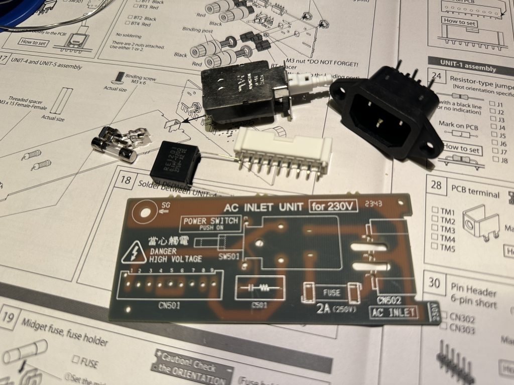
All the parts you need to assemble the power board
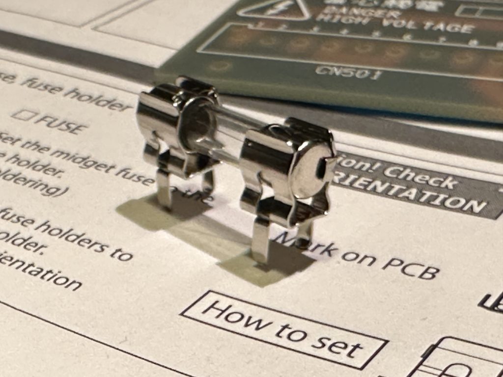
Fuse with the terminals attached
Put the mounting terminals onto one of the fuses – they only go on one way, so you can’t really mess it up. Then place the fuse with the terminals into the right spot on the board and solder the terminals in place. That way, everything will be nicely aligned and the fuse won’t be under any stress.
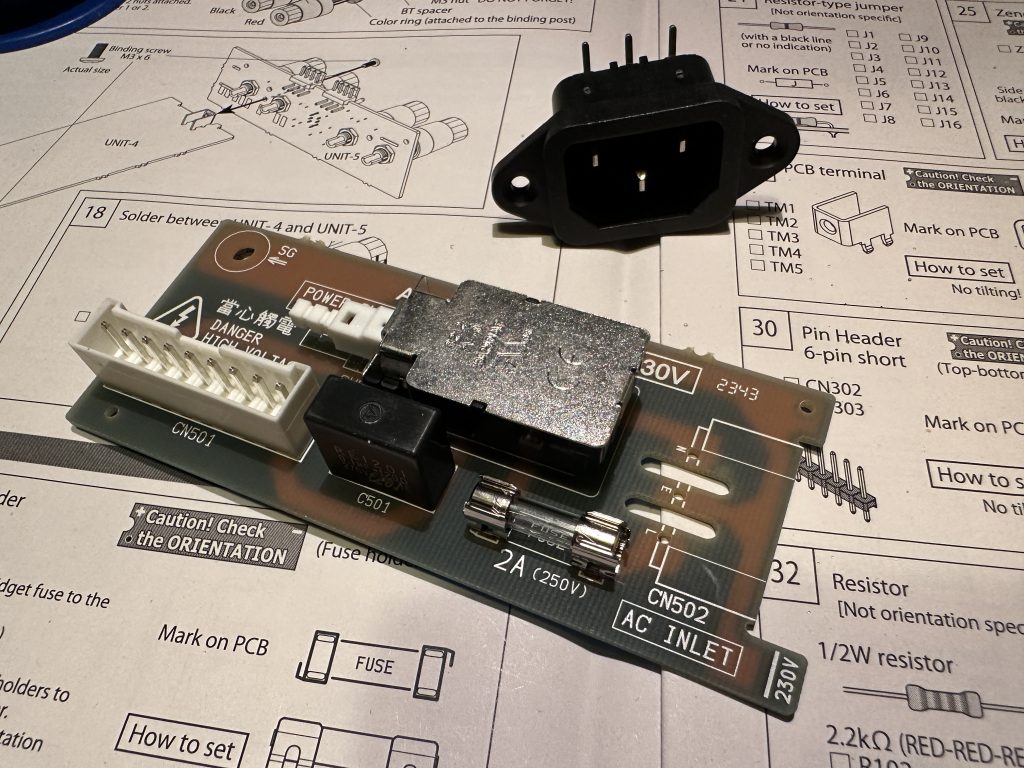
Almost finished power board
Installing the remaining parts probably doesn’t need any extra explanation. But just in case: the transformer socket only fits one way, the orientation of the spark killer doesn’t matter, and the power socket should sit flat and be pushed in all the way. Its housing should fit snugly into the cutout on the board.
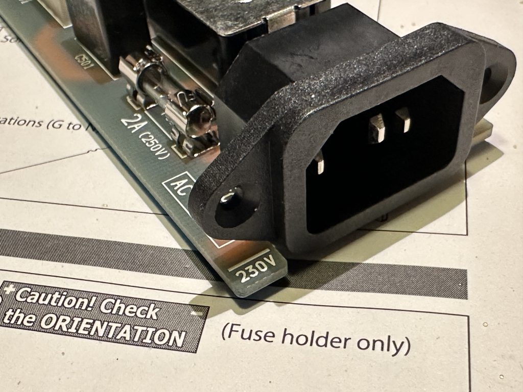
Power socket installation
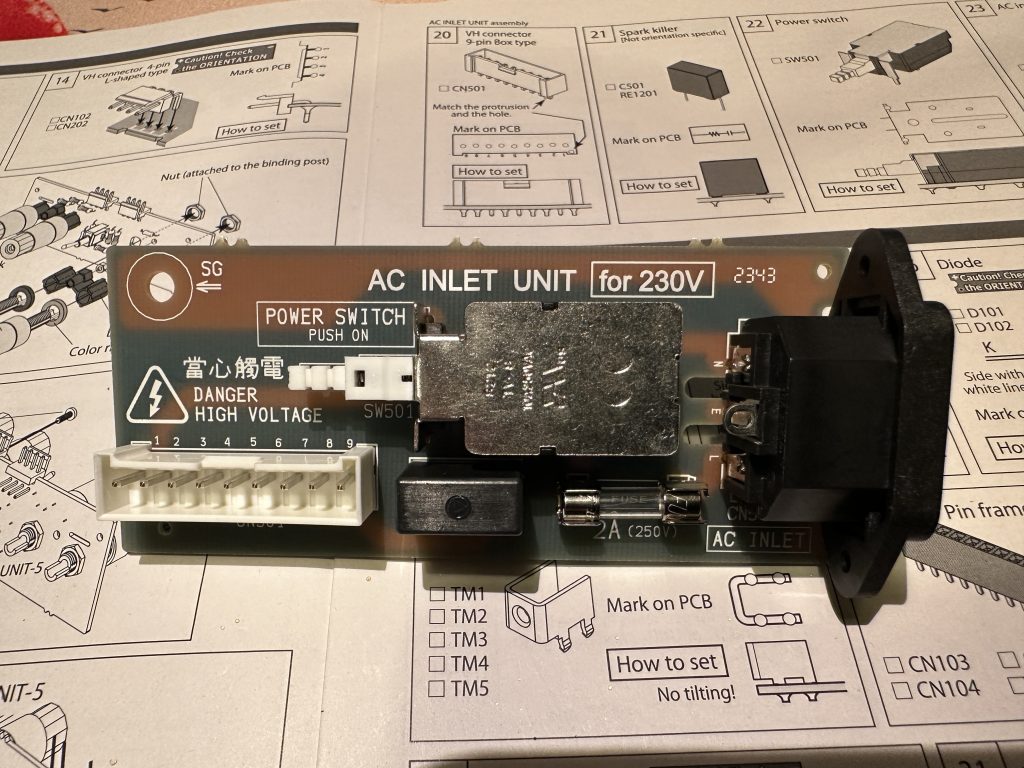
Completed power board
The finished power board gets set aside, and now, following the instructions, we move on to the main board, UNIT-1. The resistors (or actually, the jumpers) are already soldered, so let’s jump straight to the next step – the diodes. Find them among the parts: four larger ones in plastic housings and two small zener diodes in glass housings. The stripe printed on the casing shows the cathode of the diode.
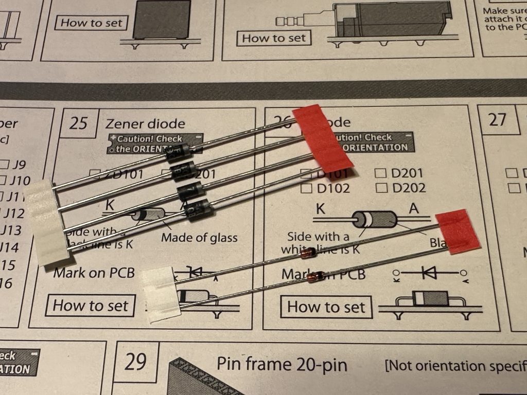
Rectifier diodes (larger ones) and zener diodes (smaller ones)
When bending the leads, it’s a good idea to first fit the diodes into the spot where they’ll be soldered and bend them a little further. If you bend them right at the body like you did with the resistors, they won’t fit properly.
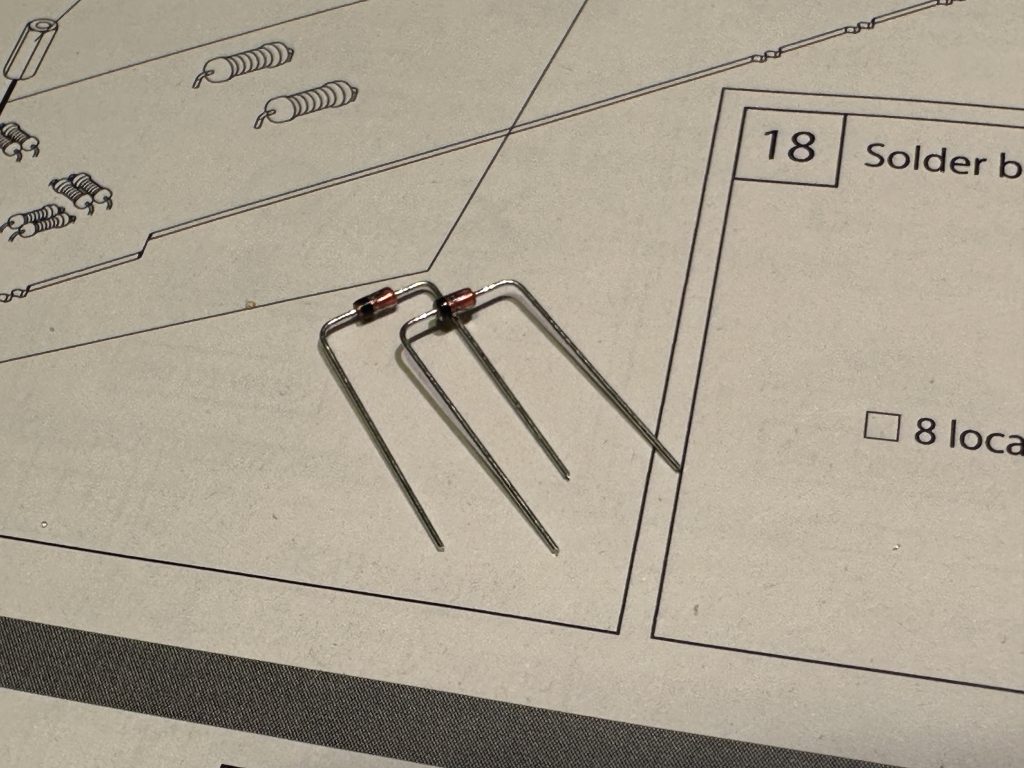
Zener diodes with bent leads
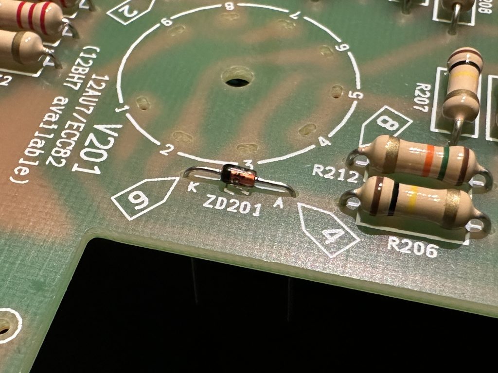
One of the zener diodes is installed. The markings [4] and [9] indicate the measurement points.
Diodes (and other components) that are on paper strips should be cut off, not pulled out. Pulling them out can damage the components.
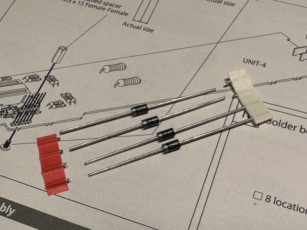
Cutting diodes off the mounting strips
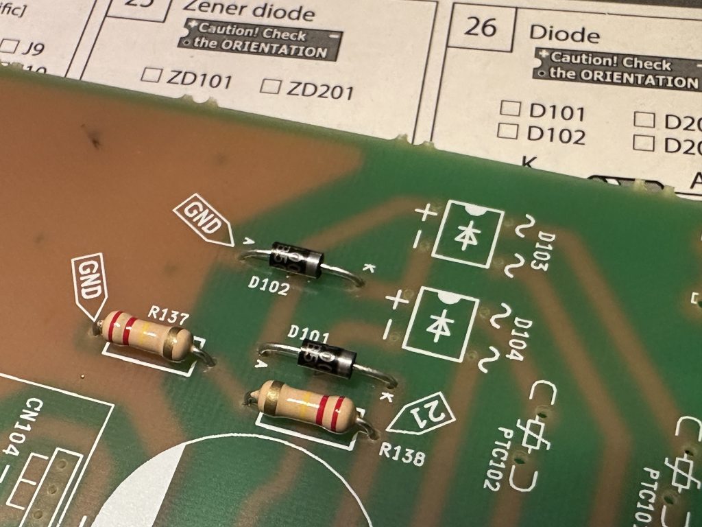
Installed rectifier diodes
After the diodes, we install the integrated bridge rectifiers – these are the four small components that look like ICs but have only four legs. They’re slightly bent outward and don’t fit straight into the holes on the board – this is completely normal, it’s supposed to be that way. The best way to install them is to first insert the legs from one side, and then gently bend the legs on the other side to fit them into the right holes. Be gentle! The legs are really thin. Make sure to double-check that the components are properly inserted into the board – the markings (+/- and /) on the board must match the ones on the component casing.
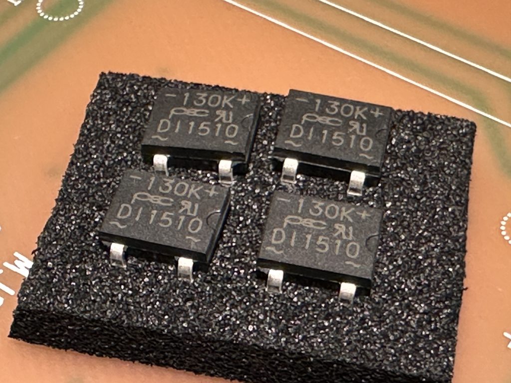
Integrated bridge rectifiers
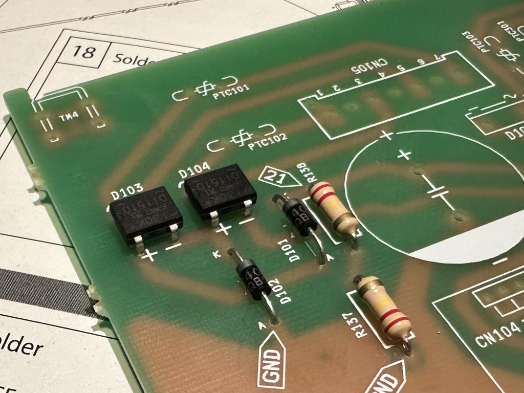
Two bridge rectifiers installed
Next, we need to install five mounting terminals – you already know how to do this, but remember to press them firmly into the holes on the board and check that they’re sitting flat and even.
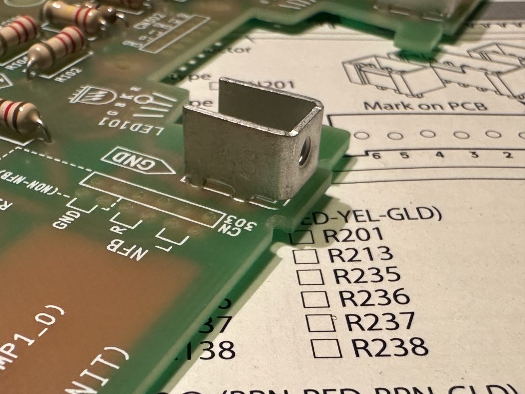
In the bag with the four strips of female goldpins, you’ll also find two yellow jumpers – these are for setting the headphone volume level. Attach them to the appropriate pins on the UNIT-4 module. At this point, it doesn’t matter which way they go on, just make sure they don’t get lost.
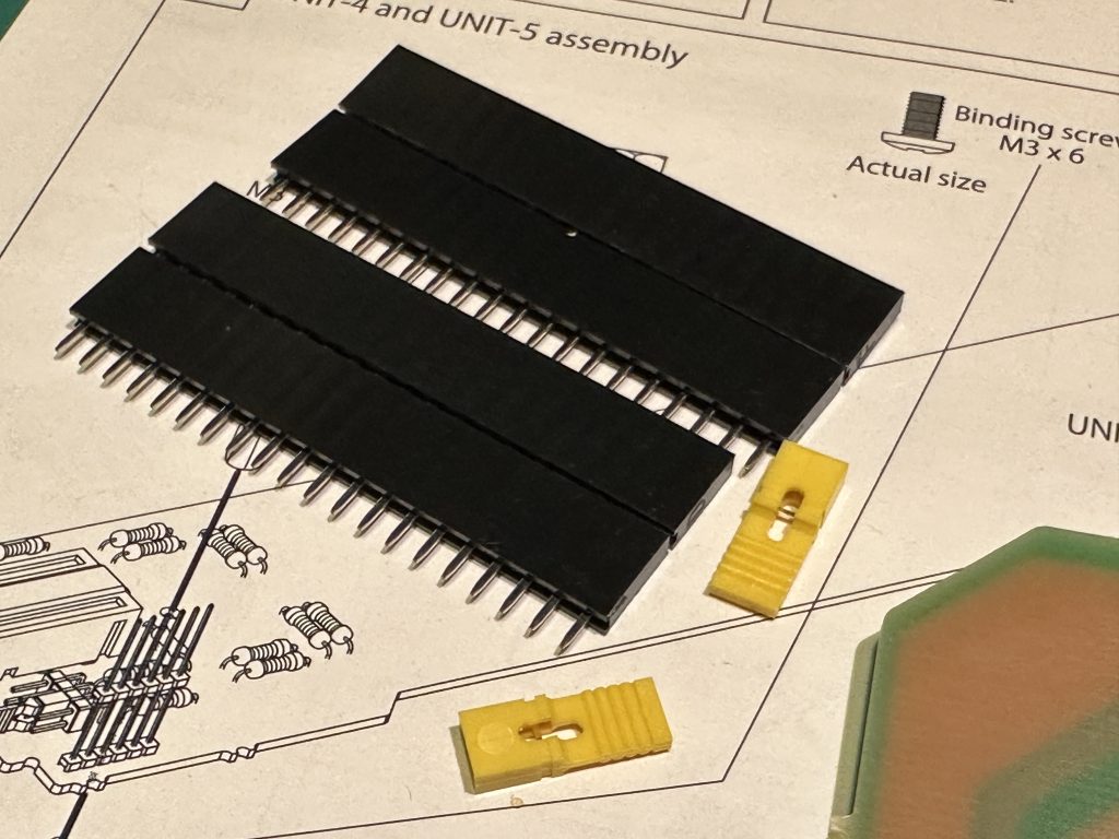
Jumpers for the headphone volume adjustment pins
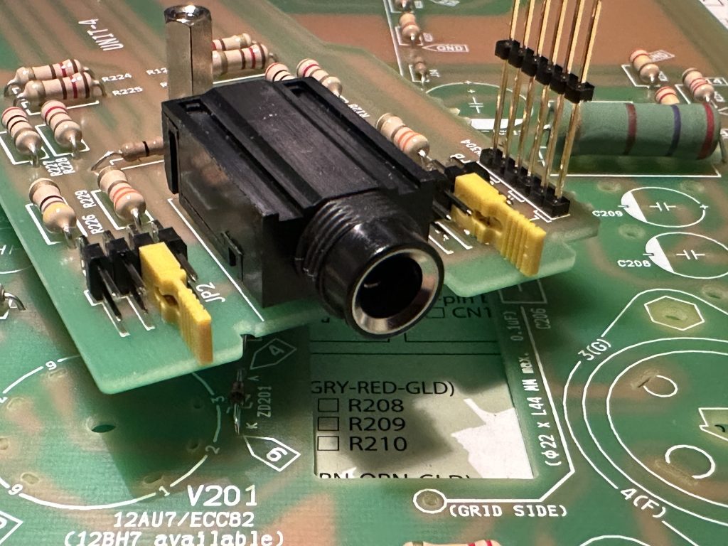
Place the jumpers on the pins in UNIT-4
The four long strips of female goldpins will serve as bases for the completed A/B modules, which are responsible for power supply and power tube detection. When installing them, make sure they are mounted vertically and, as always, pressed firmly against the board.
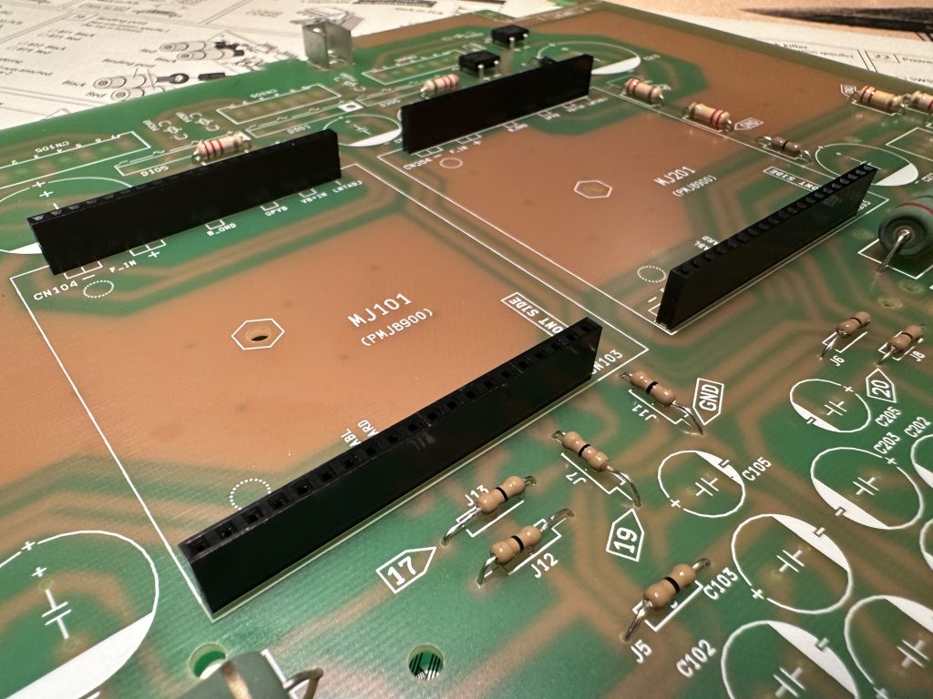
Sockets for the A/B modules
In the video below, you can see how to quickly and securely solder the pin strip.
One of the two 6-pin male goldpin strips will form half of the feedback (NFB) switch, and the other half will be used for the potentiometer connection. The long black jumpers will be really important soon, so don’t lose them.
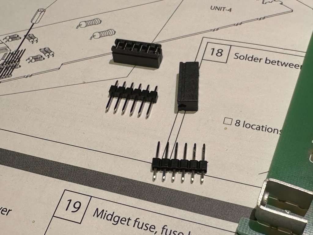
Parts for the feedback (NFB) switch and potentiometer connection
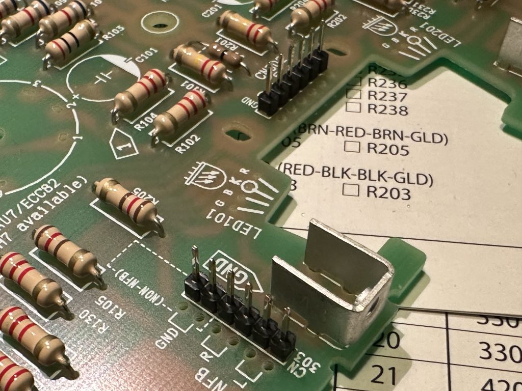
Soldered 6-pin strips
The next step is to solder the five white sockets for connecting the speaker transformers and the power transformer output. They can only be inserted into the board holes one way.
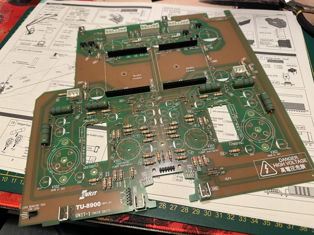
UNIT-1 with the sockets for connecting the transformers installed
Coupling capacitors, or more specifically, their type and quality, are relatively important elements in an amplifier. They’re placed directly in the signal path, so their quality heavily influences the overall sound and performance of the amplifier. The original polypropylene capacitors that come with the kit are actually quite good, and you can easily install and use them. However, audiophiles like to experiment and swap them out for other types, which is totally recommended in a DIY kit like this. Since “better” capacitors are often bigger, extra space has been allocated on the board for them – those large, elongated holes between the tubes. Additionally, to avoid the hassle of desoldering them every time we want to change them, we’ll install special pins that will allow you to easily solder a new capacitor later. Just remember, when making such a change, first desolder the original capacitor! Connecting a second one in parallel could cause problems… And, of course, NEVER do this while the amplifier is powered on – though I hope I didn’t need to mention that…
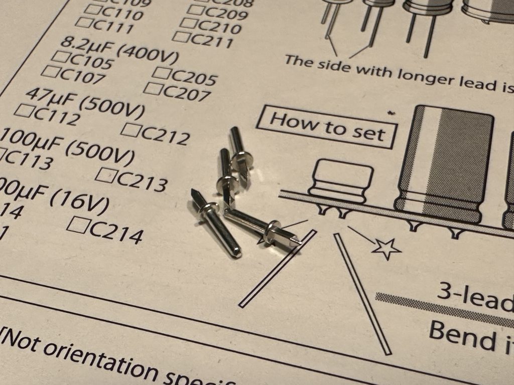
Pins for coupling capacitors
The pins need to be pressed firmly into the board and, of course, soldered on the other side.
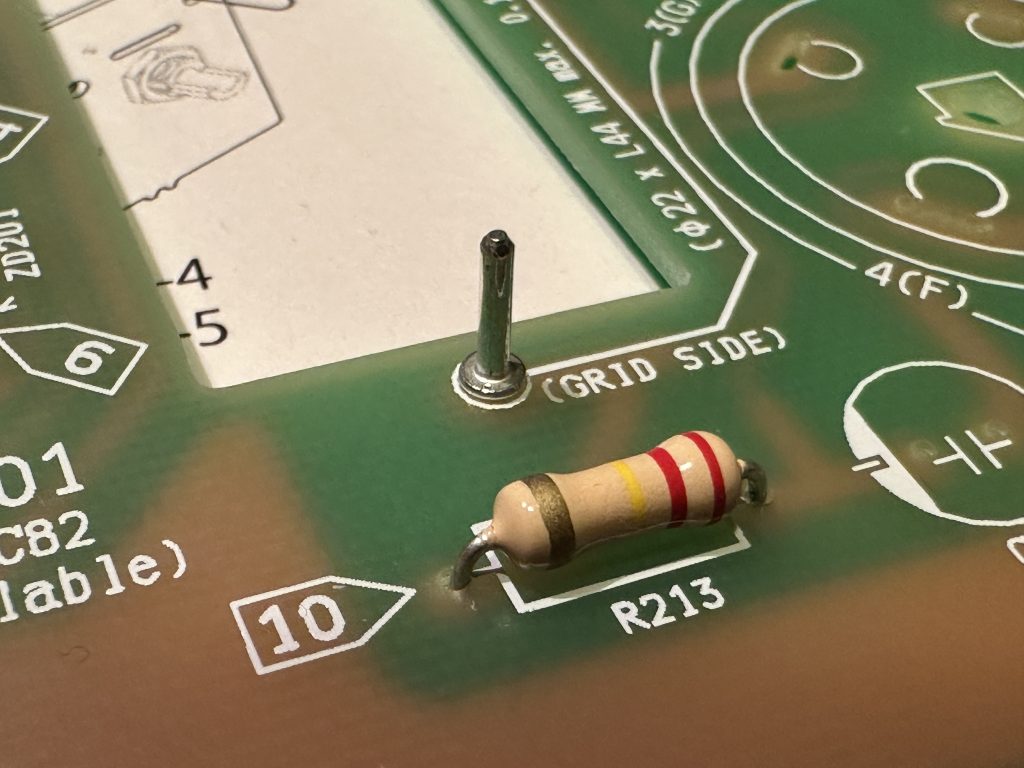
The original coupling capacitor has its dedicated spot on the board. It’s the black block with the “104” marking.
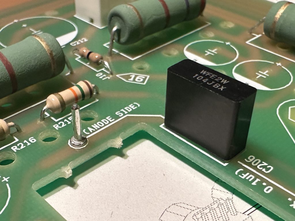
Original coupling capacitor
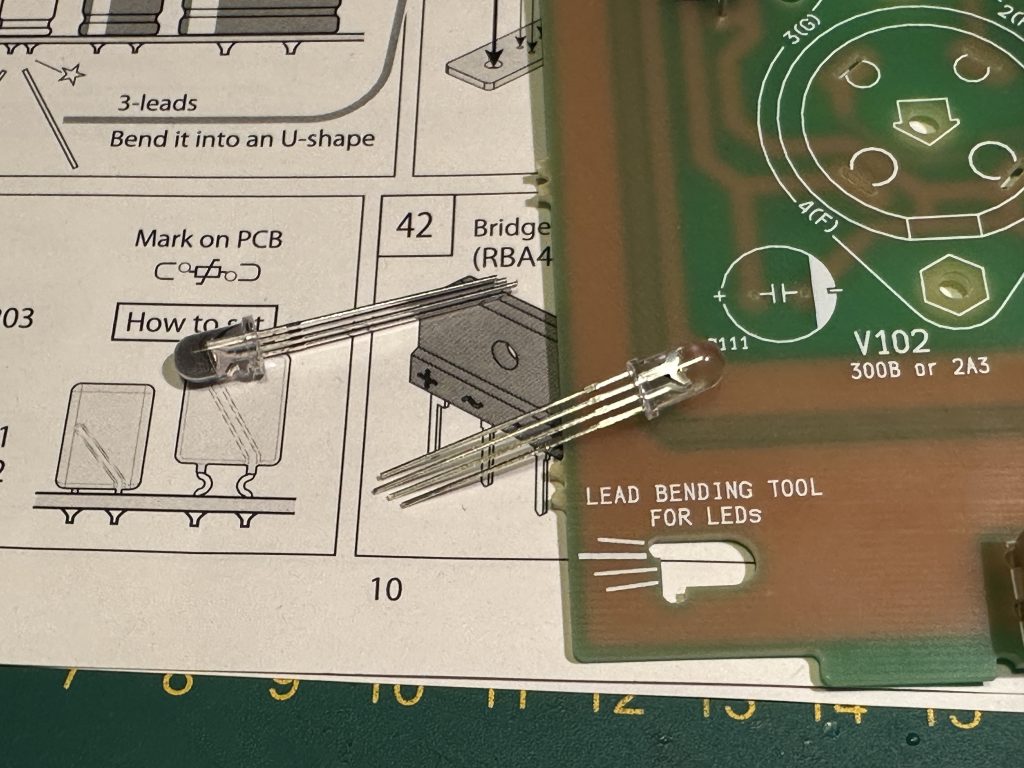
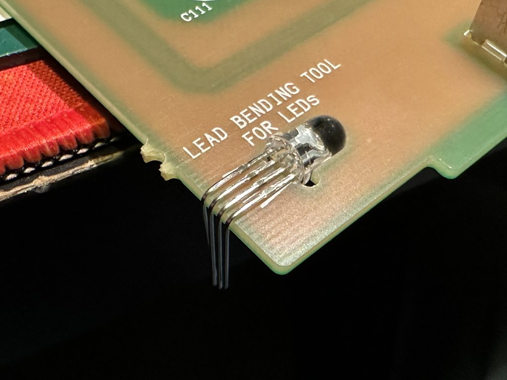
Now, we move on to the RGB LEDs, which will show us which power tube has been detected by the amplifier. On the PCB, there’s a specially designed “tool” to help bend the legs of the diodes properly. Just insert the diode into the cutout (note the legs of the diode – they are of different lengths – they should be placed as shown in the board’s markings) and bend the protruding legs at a right angle along the edge of the board. This will allow the diode to fit perfectly in its spot. When inserting the diode, remember that the longest leg is the cathode, and its position is marked with a circle.
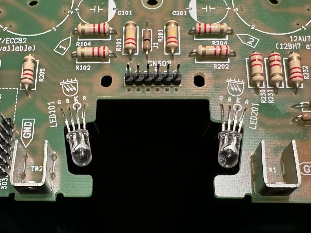
After installing the LEDs, leave them as shown in the picture. In one of the next steps, we’ll adjust them further so they shine in the right direction.
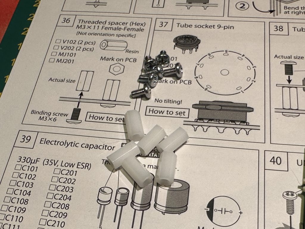
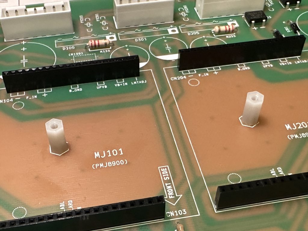
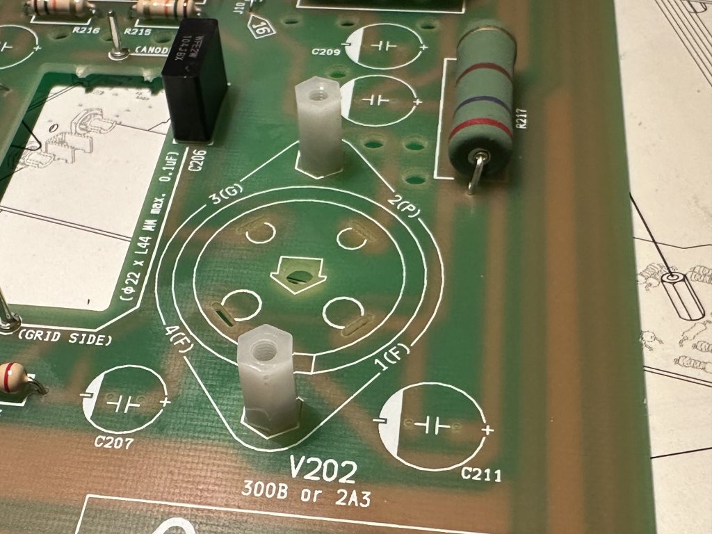
Find the plastic (or more specifically, nylon) standoffs and secure them with M3 screws in the appropriate spots. These are used to mount the A/B power supply modules for the power tubes (one standoff for each) and to secure the power tube sockets (two standoffs for each).
The sockets for the smaller tubes, like the integrated bridge rectifiers, have bent legs and don’t fit into the holes. The installation method is similar – insert one or two legs, then gently bend the others with tweezers and carefully press them into the right holes one by one. The socket only fits one way, so you can’t go wrong here. After inserting it, flip the board over and solder any two opposite legs to secure the socket in place, then check if it’s properly aligned. If it is, solder the remaining legs.
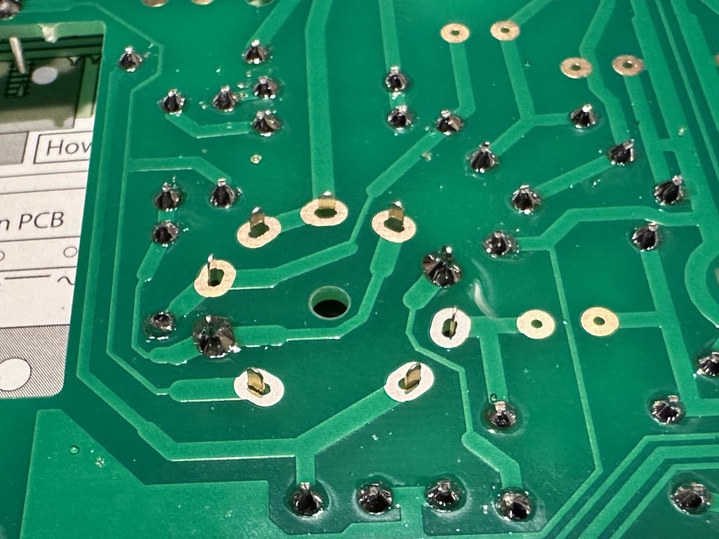
First, solder any two opposite legs
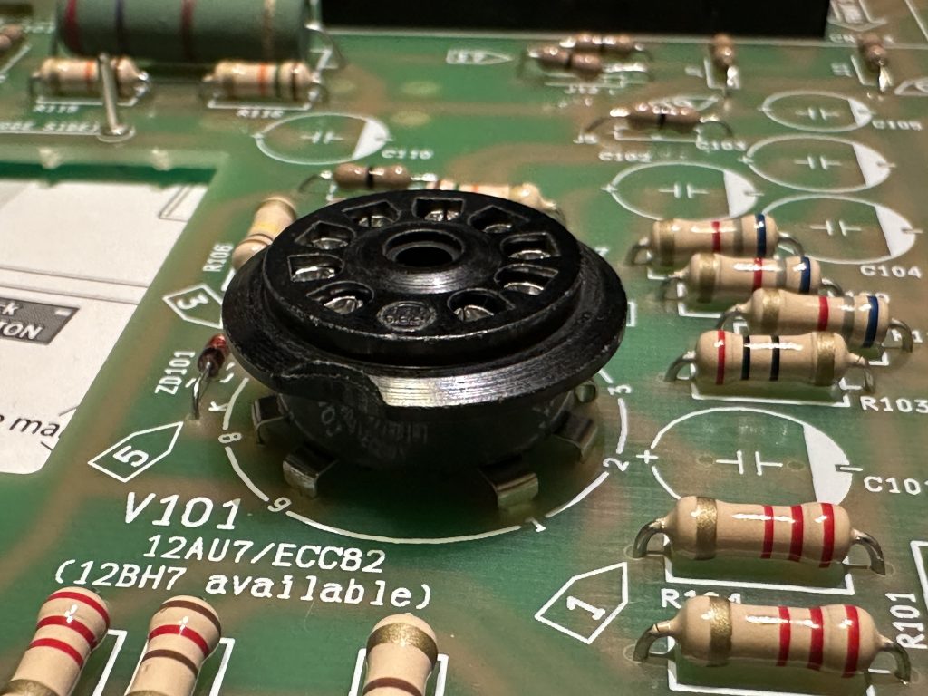
Finished, installed ECC82 tube socket
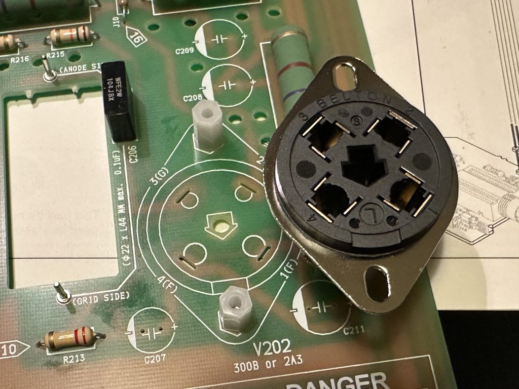
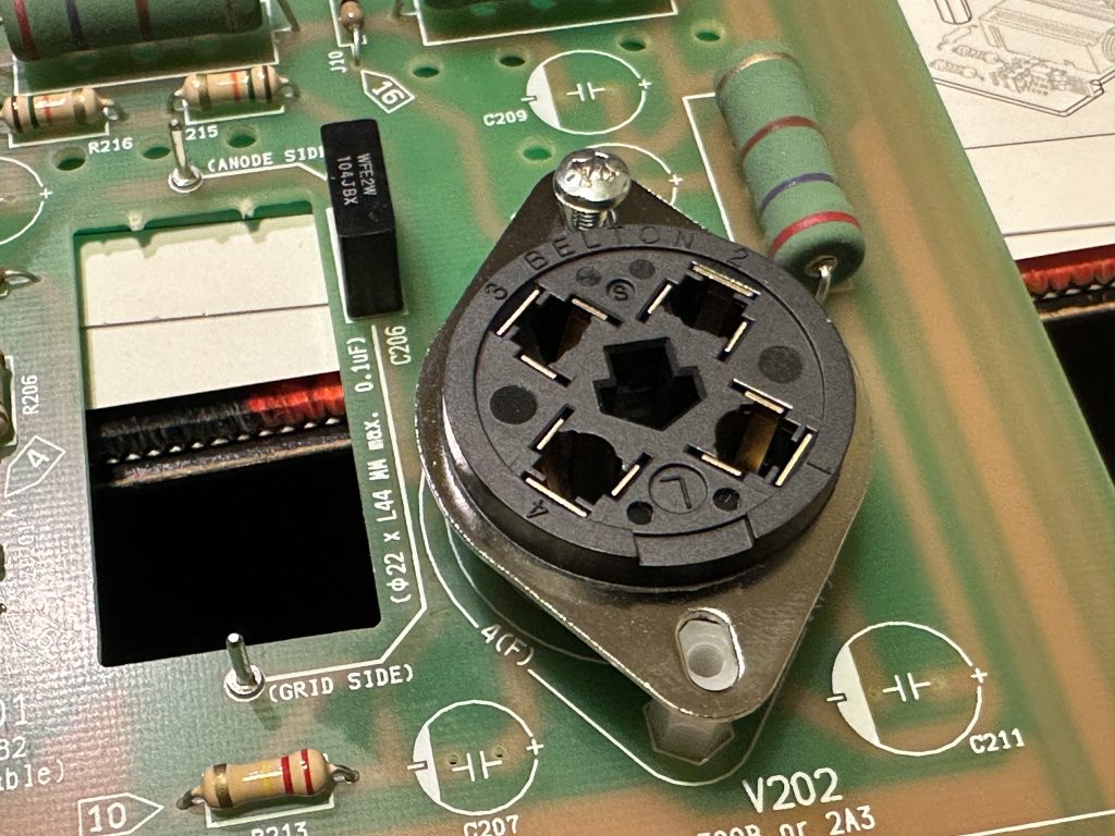
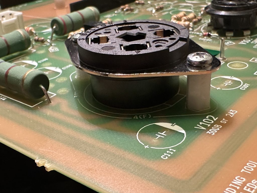
The power tube sockets require a bit more work. First, insert the socket in place, paying attention to its orientation – there’s a distinctive arrow-shaped hole between the tube pin holes, exactly the same as the one marked on the board. The socket must be positioned so that the “arrow” is pointing in the same direction. Then, screw the socket onto the standoffs using M5 screws. Only after securing it, flip the board over and solder the socket legs.
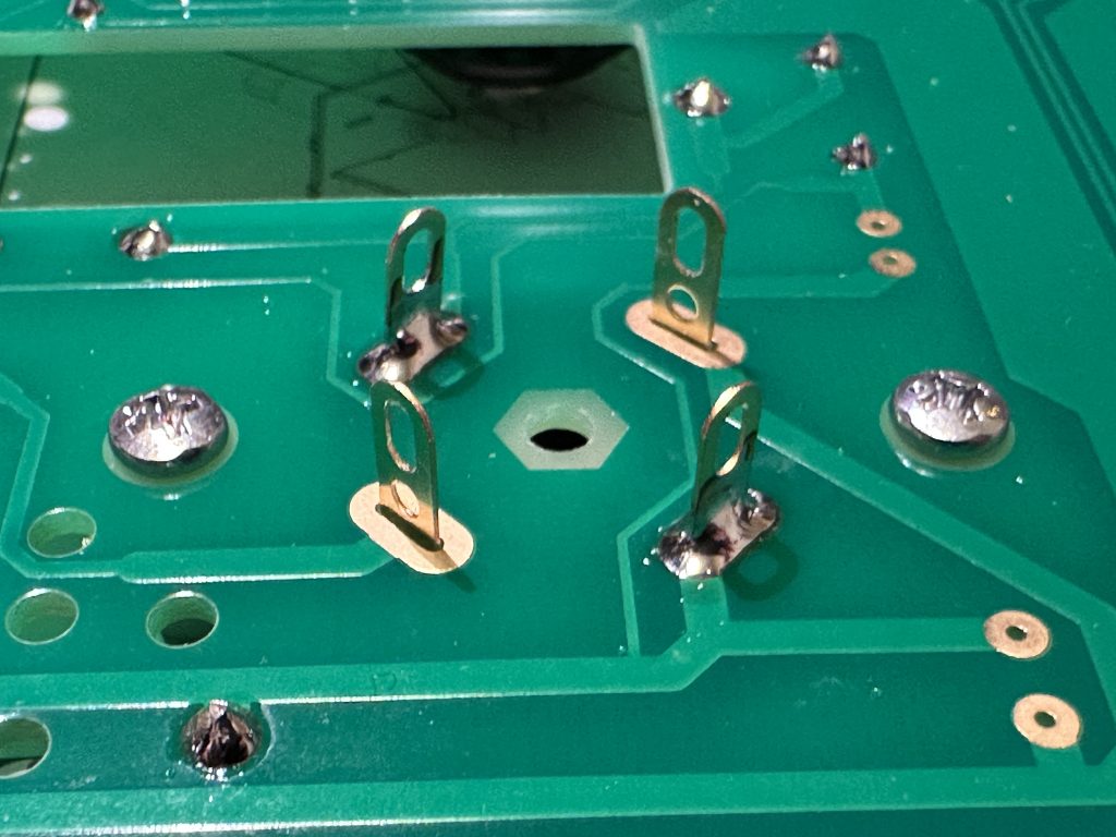
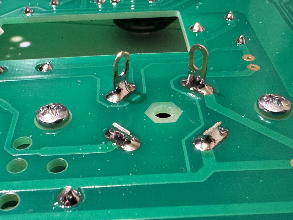
After soldering the legs, cut off the remaining protruding parts.
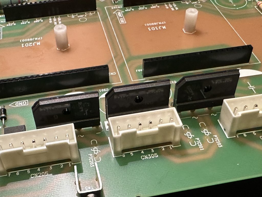
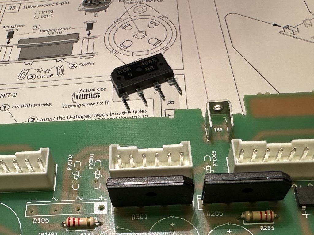
I’d suggest a small change in the assembly order – I recommend installing the large, integrated bridge rectifiers now. The reason is that according to the original instructions, their installation comes after the capacitors, which can make it quite tricky to handle the bridge rectifiers. It’s easier to do this now. Note that the cut corner of the bridge housing is marked on the board with a white square. To be sure, you can also check if the polarity markings on the board (+/-) match the leg descriptions on the bridge housing.
It’s time to install the electrolytic capacitors. It’s very important to maintain the correct polarity here. Each electrolytic capacitor clearly marks its legs as + and -, or in some cases, marks the negative leg differently. The negative leg is also shorter. Also, note that the capacitors are positioned on the board so that the negative legs in each section are pointing in the same direction. In the left channel, the negative legs are on the right side, in the right channel on the left side, and in the common parts, they point downward. This is all to make it easy to visually check after installation that all the electrolytic capacitors are soldered correctly. If any of them are soldered incorrectly, it will be much easier to spot. This is important because a wrongly installed electrolytic capacitor can “explode” when the power is turned on, especially with the high voltages present in a tube amplifier. So, make sure to pay extra attention to this.
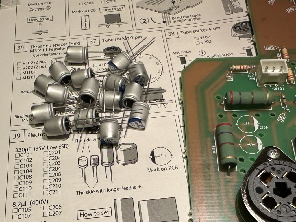
Electrolytic capacitors
I suggest following the same approach as with the resistors, meaning installing all capacitors of the same value as one group. It’s best to start with the smallest ones – that way, when you flip the board, you can rest it on the capacitors and easily solder all their legs.
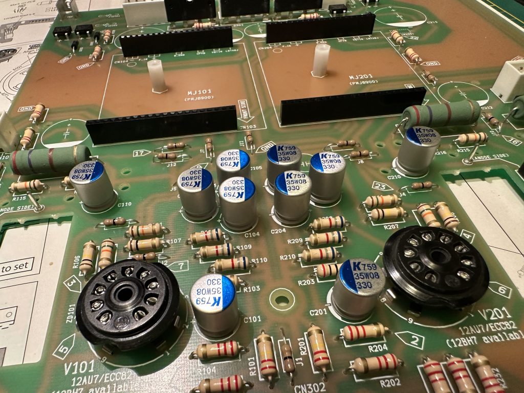
The UNIT-1 board with partially installed capacitors. Notice that the cathodes of the capacitors (marked with a blue stripe) are facing the same direction within each section of the board.
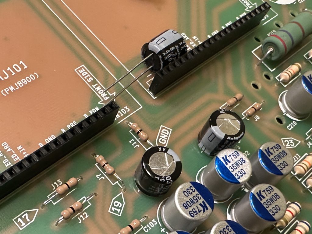
Install the capacitors one by one, working your way up to the largest ones. These have slightly different legs – much thicker and bent. However, they fit easily into the designated holes, you just need to press the capacitor firmly against the board until it “clicks” into place.
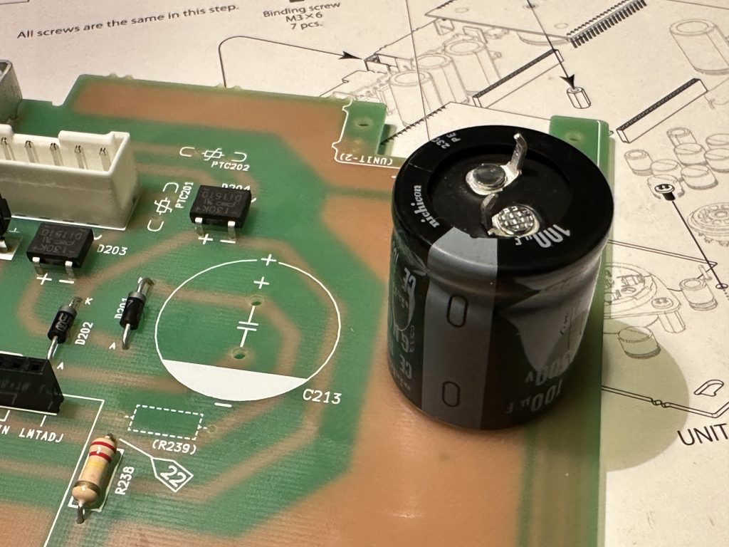
The largest electrolytic capacitor
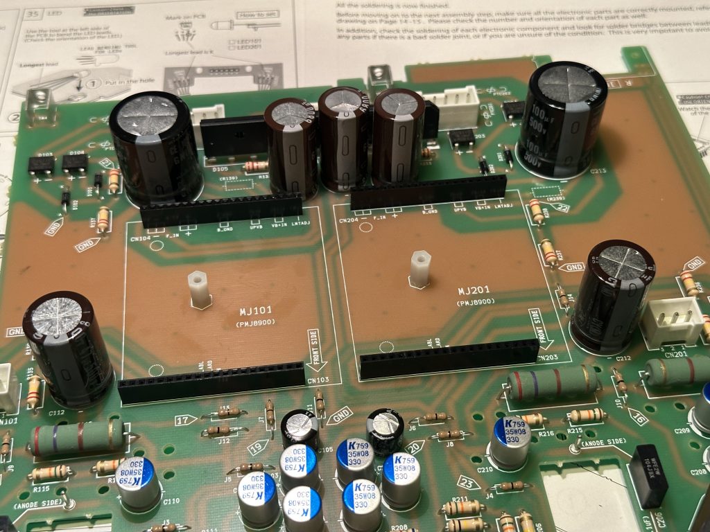
Board with installed capacitors
The installation of the sockets we soldered onto the UNIT-2 board at the very beginning is a bit tricky, but definitely doable. As shown in the picture below, flip the UNIT-2 board over and align it with its mounting position.
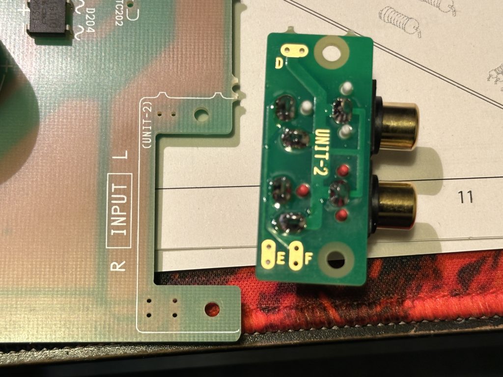
Installation of the board with input sockets
The easiest way is to initially secure the board with one M3x10 screw. Just enough to hold the board in place, but still allow for a little movement.
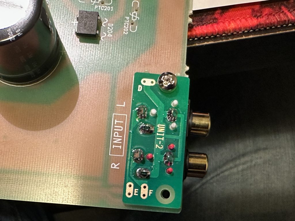
Earlier, I mentioned not to throw away the cut-off legs of the components. Now, we’ll need them. Take one of the medium-thickness legs and bend it into a U-shape. This bent leg should be threaded through the holes in UNIT-2 (marked with the letters D, E, and F – pick one letter) and also through the corresponding holes in the UNIT-1 board. In other words, the leg must pass through both boards and stick out on the other side. You’ll need to make three such jumpers and thread them through the appropriate holes. If you don’t screw the board in too tightly, it will be much easier to do – tight screwing often misaligns the holes, making it impossible to pass the jumpers all the way through.
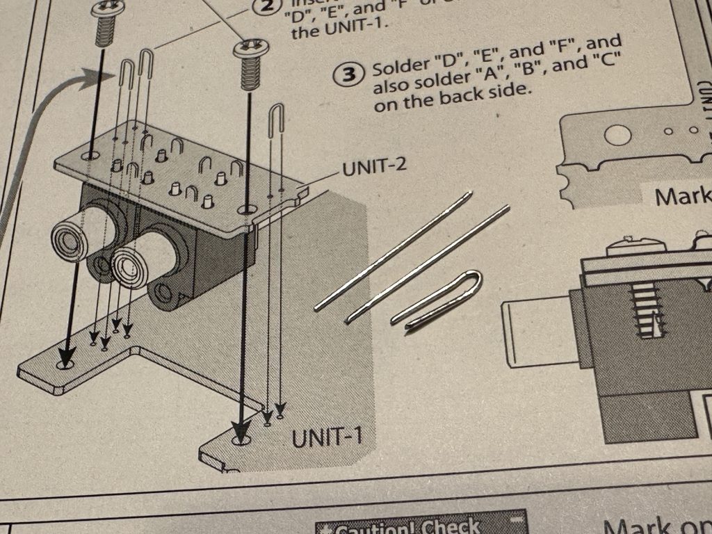
Preparing the jumper for the installation of the board with input sockets.
Once all the jumpers are in place, solder them from the top and then tighten the board with both screws.
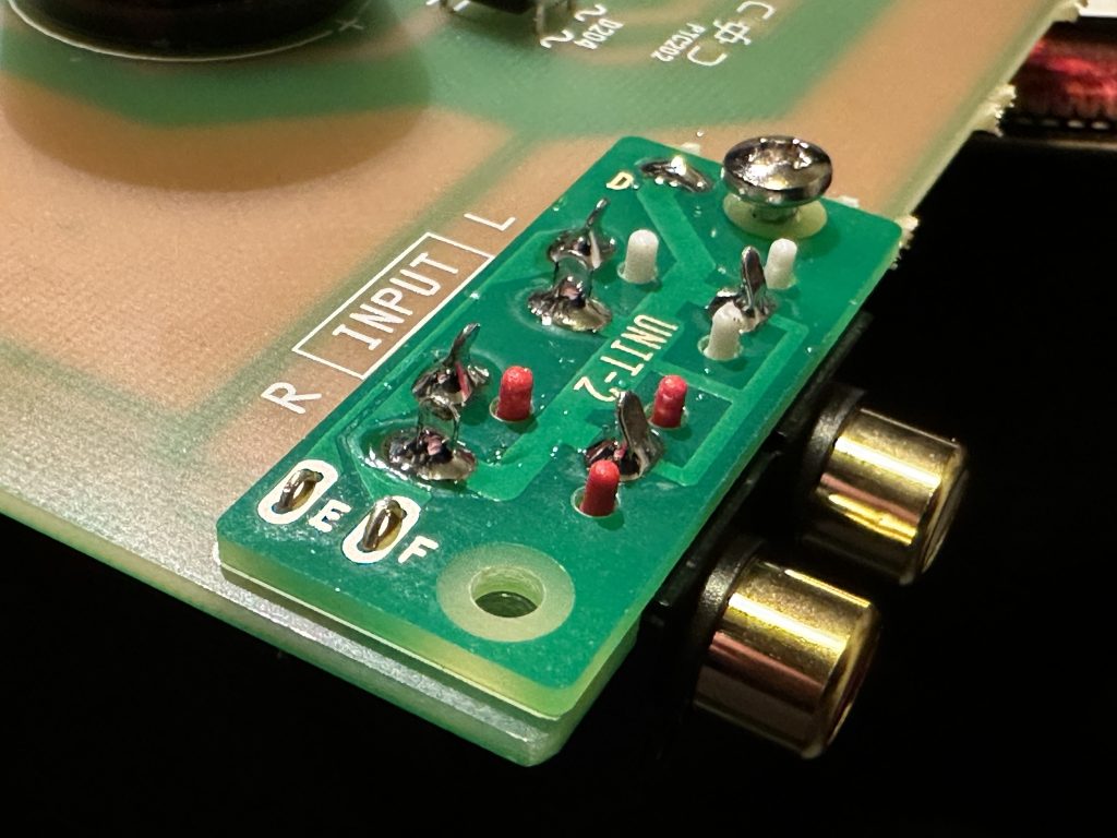
Soldered jumper D
Now we can flip the board to the other side, solder the jumper legs, and trim off the excess.
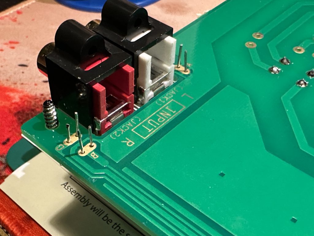
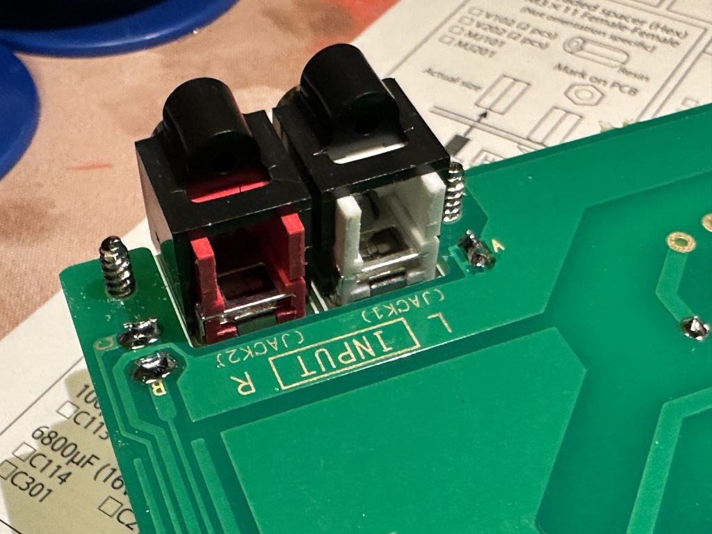
The installed input socket module looks like the one in the picture below.
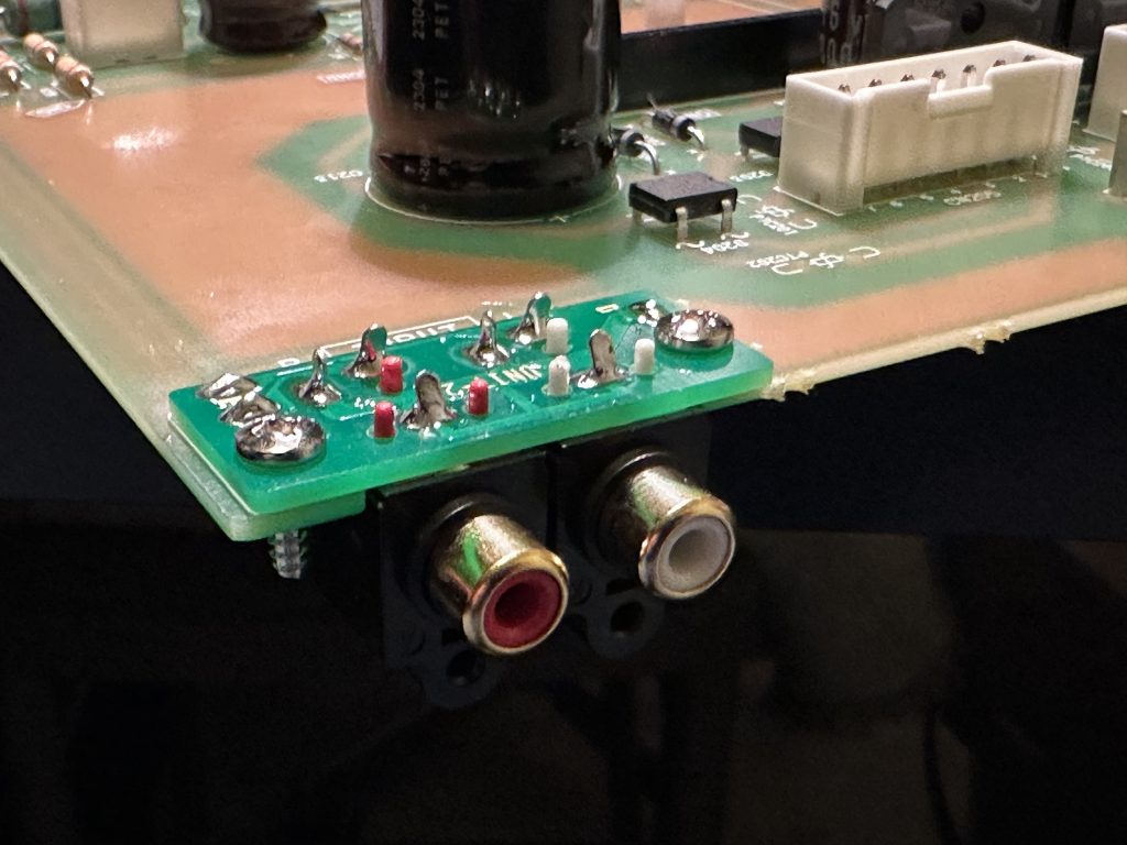
The installed input socket module.
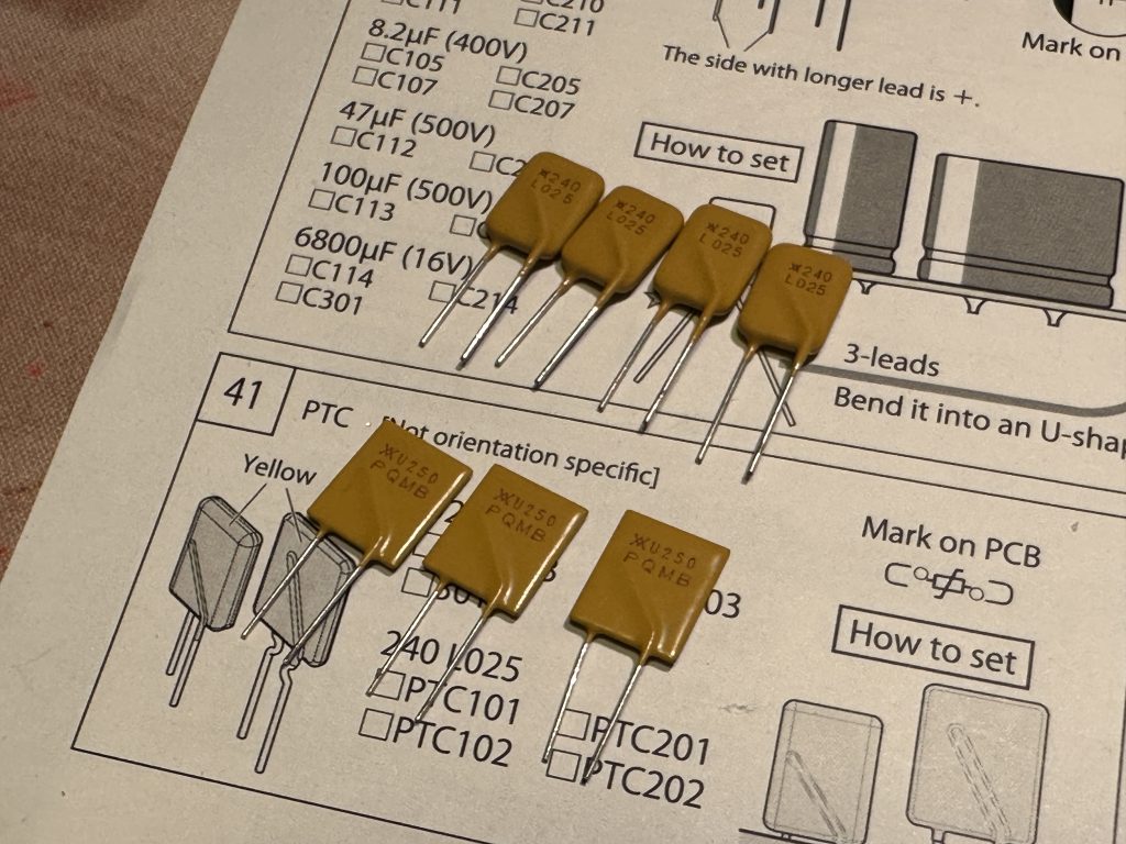
Since we’ve already installed the rectifier bridges earlier, the only remaining components are the PTC protection elements. Be careful—there are two types of them.
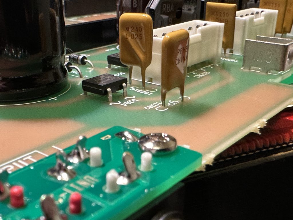
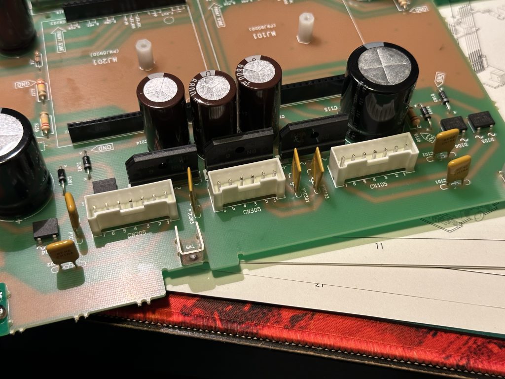
We’ve reached the end of the soldering stage. It’s a good idea to carefully inspect the entire board from both sides to make sure everything is in place. You can, for example, hold the board up to the light; any empty holes will be clearly visible. Make sure to check these areas carefully, as almost all holes should be occupied. Almost, because there are places without components, marked with a dashed line on the board, and their description is in parentheses. These are spots for elements that were used during the design and testing stages of the amplifier but were ultimately not included in the final version for production. Most of these elements were completely removed from the board, but a few remained. The decision to remove them was made after the PCB batch was already produced.
In addition to checking for empty spots, we should also pay attention to whether all the components are properly soldered, if nothing is loose, and if there are no shorts between the tracks, etc. This may seem unnecessary, but it really makes sense — often, taking the time to inspect the board can help catch any potential issues early on.
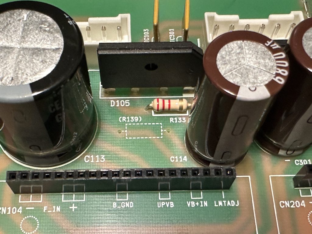
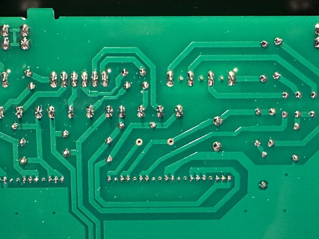
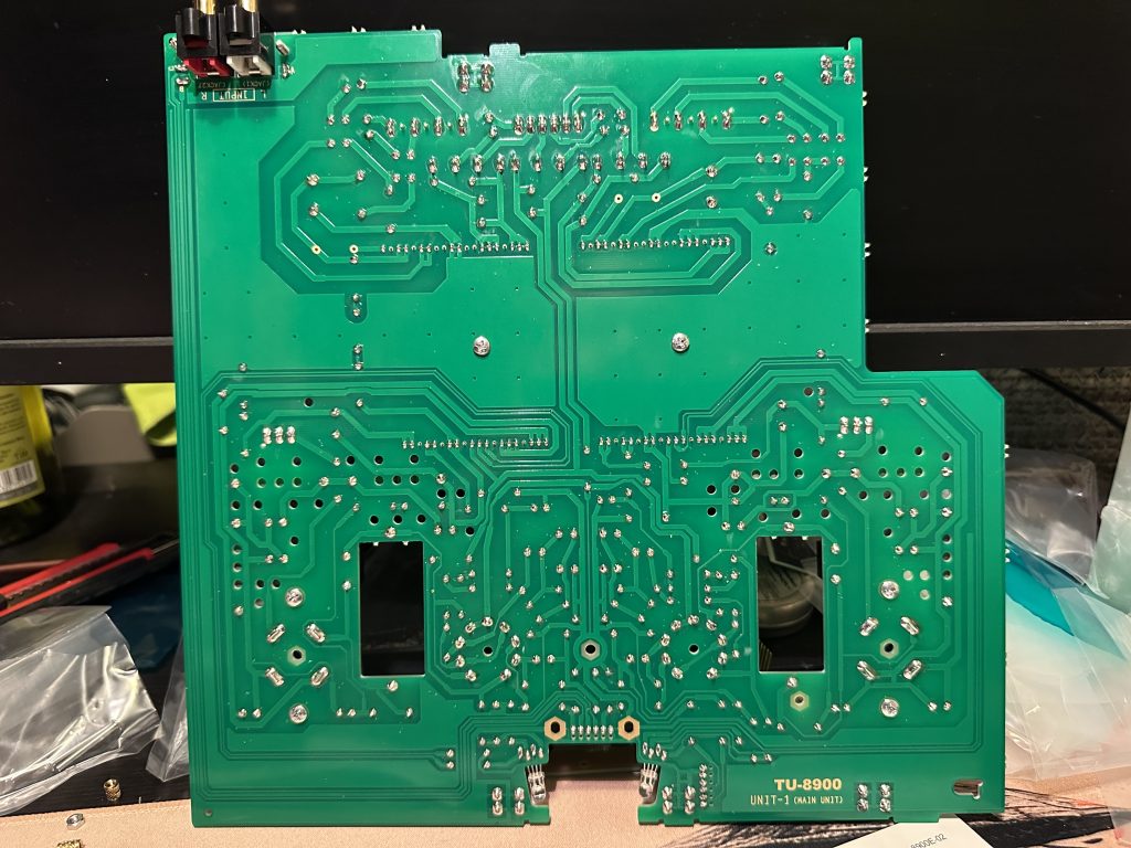
Checking the boards after assembly. The empty holes for components that didn’t make it to the production stage are visible.
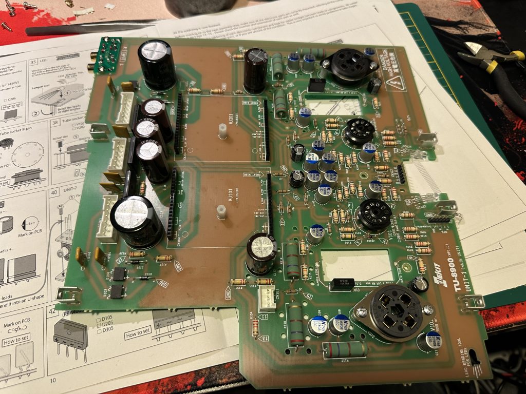
Assembled (soldered) UNIT-1 board.
We already have all the boards soldered, so we can move on to the mechanical assembly stage. It’s best to make plenty of room on the table now – the chassis is quite large, and we’ll need to rotate it in all directions.
If you are already prepared for the next steps, I invite you to read the next part.

You must be logged in to post a comment.