ELEKIT TU-8900 or how to build a tube amplifier – part 2
UNIT-4
At the very beginning of this report, I strongly recommended following the instructions during assembly, and I still encourage you to do so, but… with one small exception. We’ve reached the point where we begin assembling the resistors, and according to the manual, we should now find one of them. Specifically, it’s a jumper in the shape of a resistor. You should take out two pieces from the bag and solder them into the UNIT-4 board at positions J17 and J18. Then set the remaining jumpers aside. After that, take two 3.3 Ω resistors for positions R129 and R229, and so on.
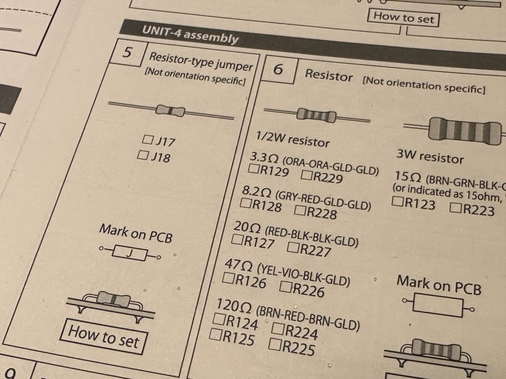
The order of proceeding according to the instructions.
This method is definitely OK and makes sense. However, it is also time-consuming and, in my opinion, a bit cumbersome. The resistors are similar to each other, there are many of them, and finding the correct values in all of them can be tricky. It’s easy to make a mistake, even though, in most cases, resistors of the same value are placed in the same bag (WARNING! – This isn’t always true!). Therefore, I’ll suggest a change for the resistors (and later for capacitors!).
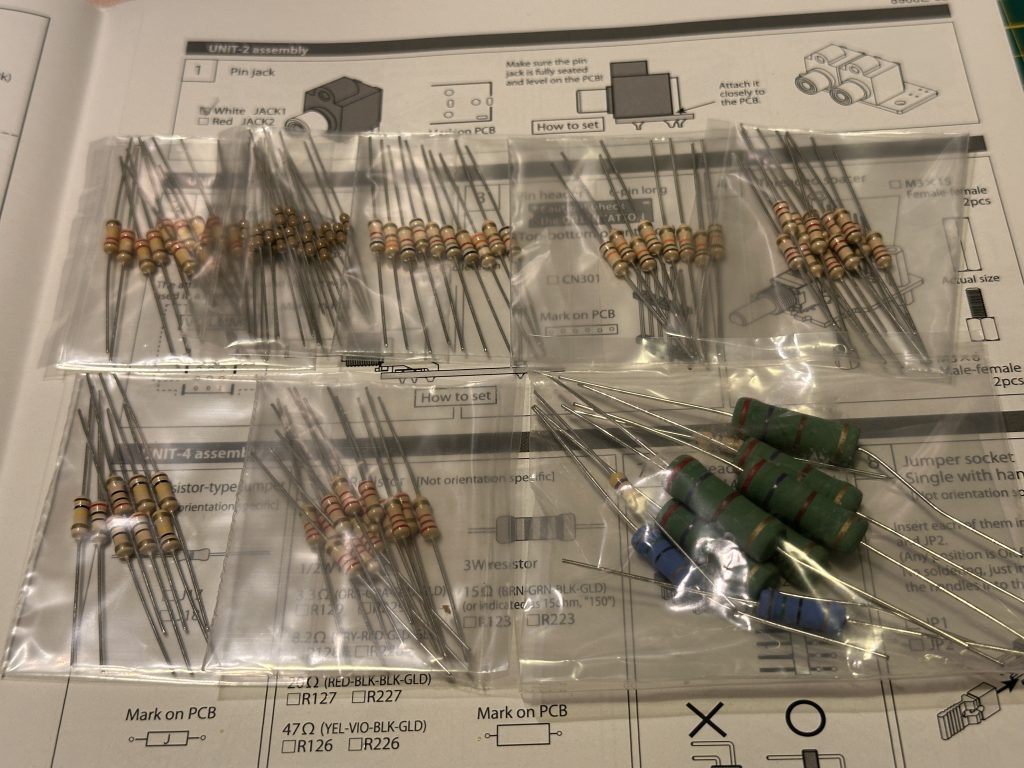
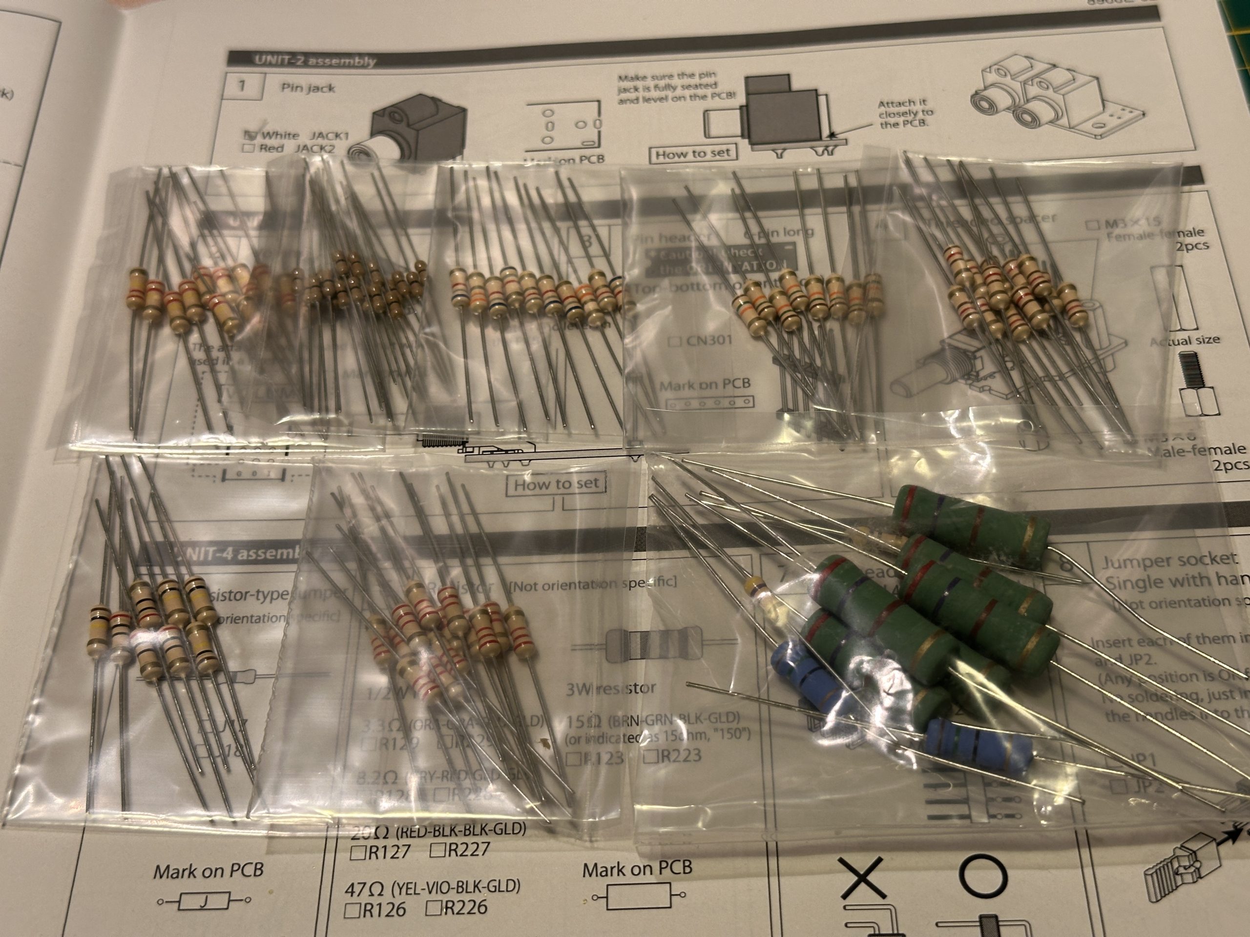
All the bags with resistors.
First, find all the bags with resistors and set them aside in a separate pile. Choose one of them (but with the small 1/2 W resistors, not the large ones) and take out all the components. Check if they all have the same barcode marking, identify it (or measure the value), and then look for that value in the instructions among all the resistors for that specific board.
If there are more resistors than listed, it means that the same value should also be installed on other boards. Similarly, if a specific value is not on the list, it will definitely be on the list for another board. Once all resistors of a certain value are installed, take the next bag and repeat the process. This way, you can quickly, effectively, and accurately install all resistors on all boards without the tedious task of searching for specific values.
The bag I got first, contains resistors with the code RED-RED-YELLOW-GOLD. According to the resistor color code table, this corresponds to a value of:
- RED – 2
- RED – 2
- YELLOW – 104
- GOLD – 5%
Which gives 2,200 ohms (2.2kΩ) ±5% tolerance.
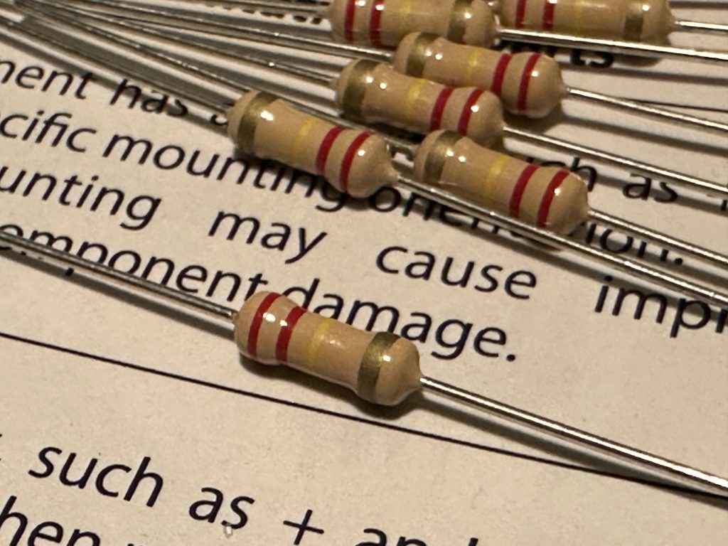
Resistors from one bag.
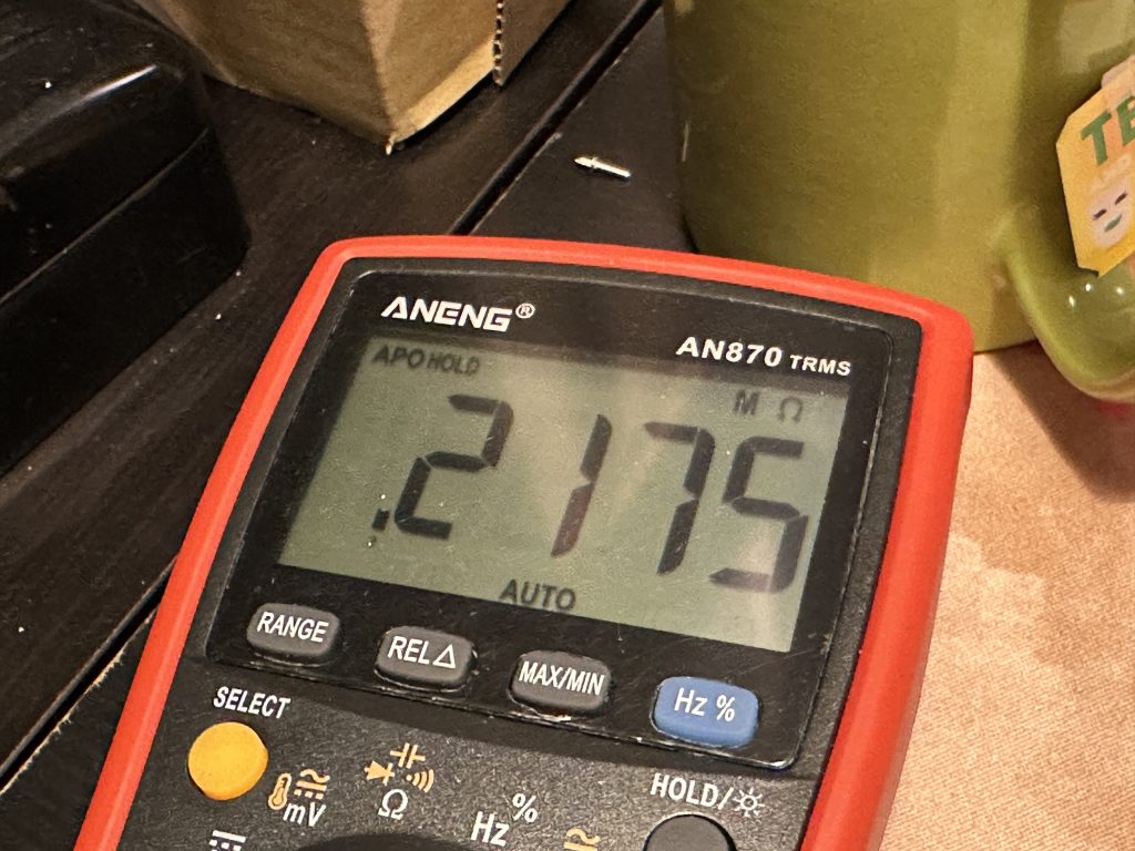
The result of measuring the resistor value.
Search for this value on the resistor list for UNIT-4… it’s not there. So, check the resistor list for the next module… and there it is! For UNIT-1, the value is 220 kΩ (RED-RED-YEL-GOLD), and the colors match. It needs to be installed 12 times. There were also 12 pieces in the bag, so install all of them on the UNIT-1 board.
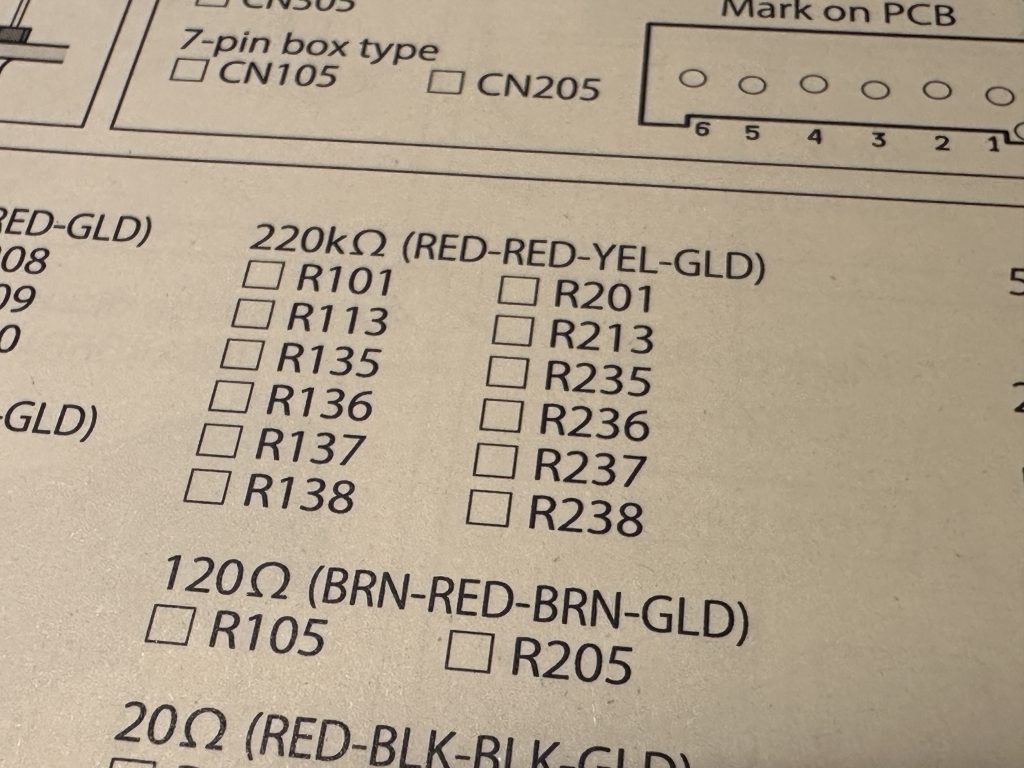
Resistor list for the UNIT-1 board.
Personally, I first bend the leads of all the resistors that I’m about to mount. I hold the resistor with one hand while using a finger from my other hand to bend one of the leads at a right angle. Then, I do the same with the other lead and move on to the next resistor. After a short while, all the resistors are ready to be inserted.
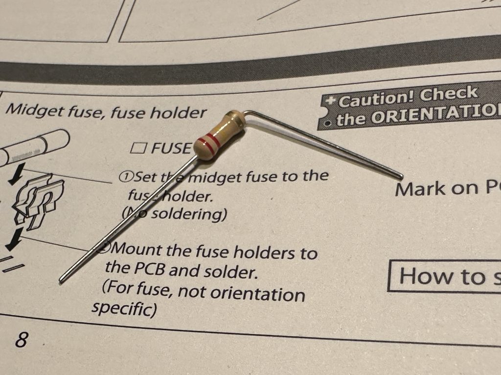
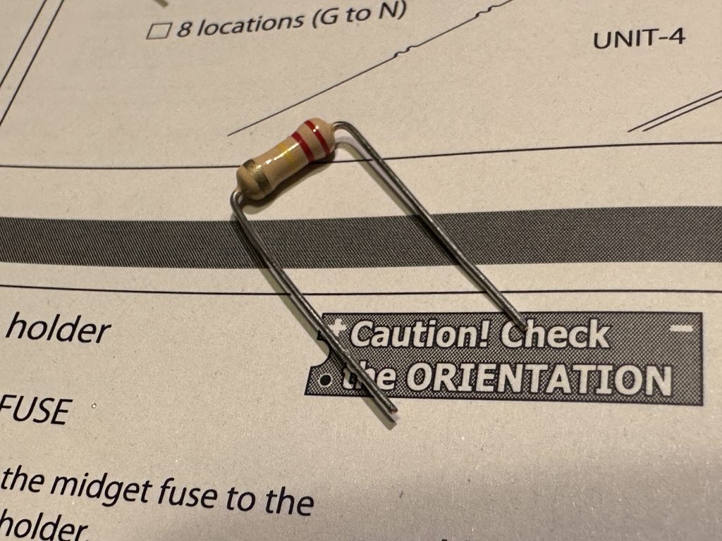
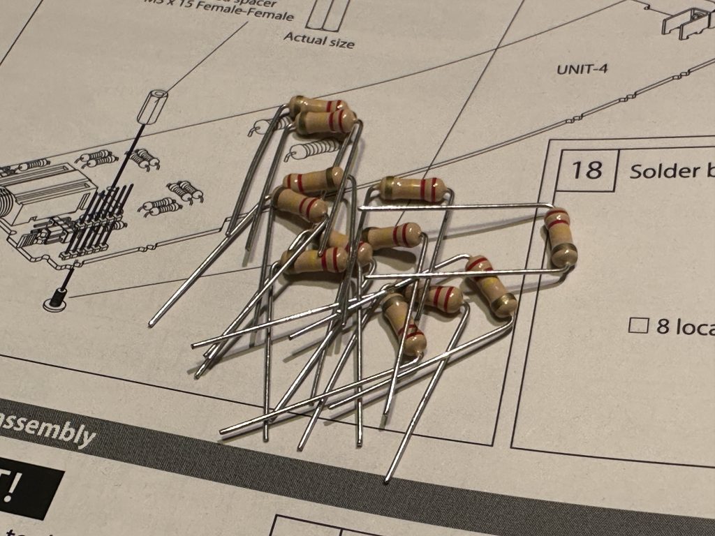
Preparing the resistors for assembly.
Take the UNIT-1 board and begin searching. Here’s a small tip: as you can see, the resistors on the list are placed in two columns. On the left are R1XX, and on the right, R2XX with their corresponding numbers. In all ELEKIT kits, elements marked R1XX or C1XX are for the left channel, while R(C)2XX are for the right. Moreover, on the boards, these components are generally arranged similarly: “ones” are on the left side, and “twos” are in roughly the same position but on the right. While this rule isn’t always strictly followed (sometimes it’s just not possible), you can generally assume that this is the case. If you can’t find a component that way, then start looking elsewhere. You might also encounter R3XX elements—these are typically found in the power supply section (shared for both channels) or in other sections where the division between channels isn’t explicitly defined, and you’ll have to search for them differently.
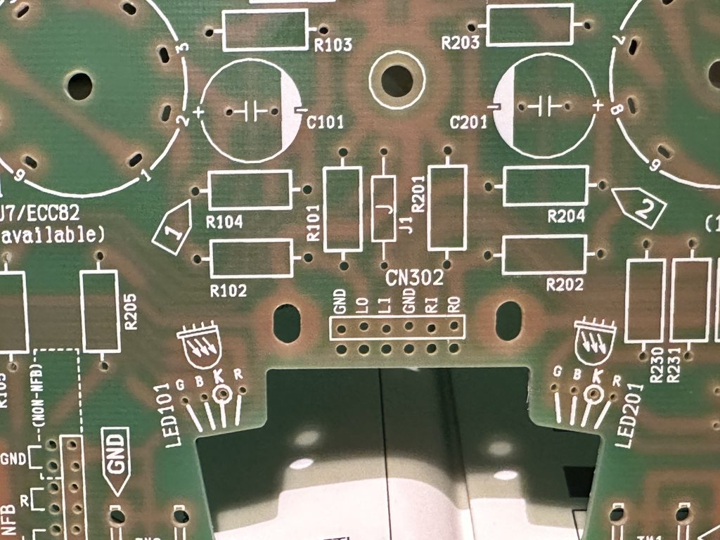
The location of resistor R101.
Return to our board and resistor R101 – let me give you a hint, it’s in the center, right next to that strange cutout. As you can see, R101 is on the left, and R201 is on the right 🙂 Ha! Now, take the resistor and insert it into the holes on the board, following the diagram on it, with no particular regard for the direction of insertion.
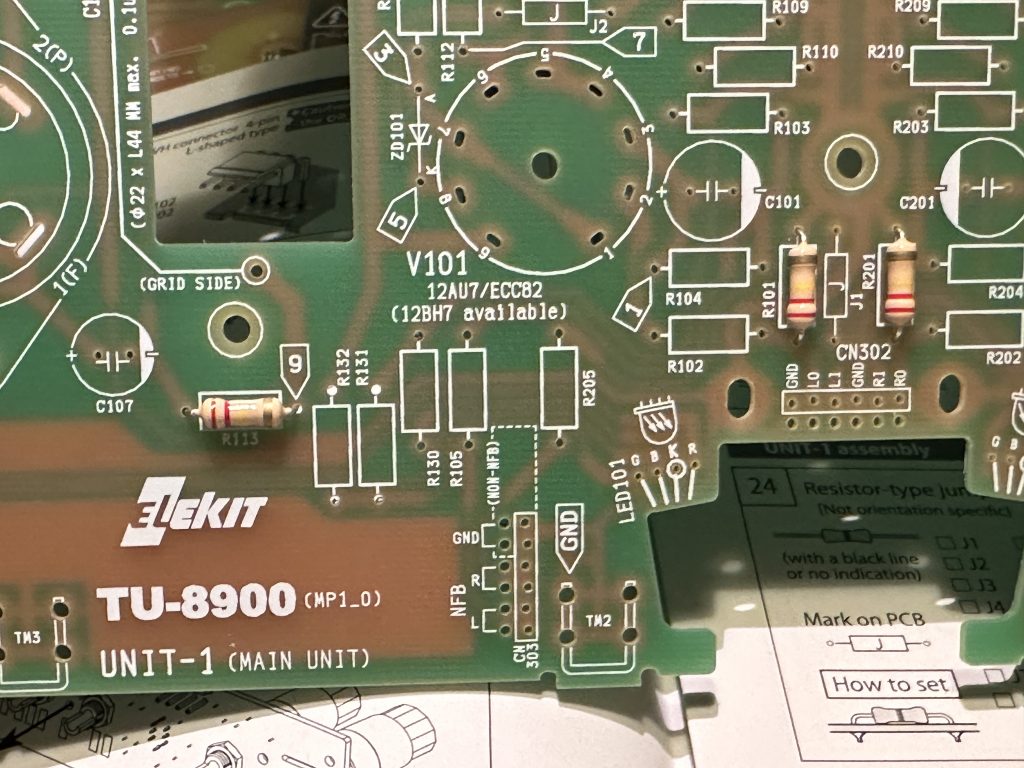
Resistors R101 and R102 are in place.
Insert the resistor all the way in so that it lies flat on the board. Sometimes it will stay in place without issue and won’t fall out when the board is flipped over, but other times it may stubbornly fall out. Since we want to insert all the resistors of this value (12 pieces) first and then solder them, it’s best if they don’t fall out.
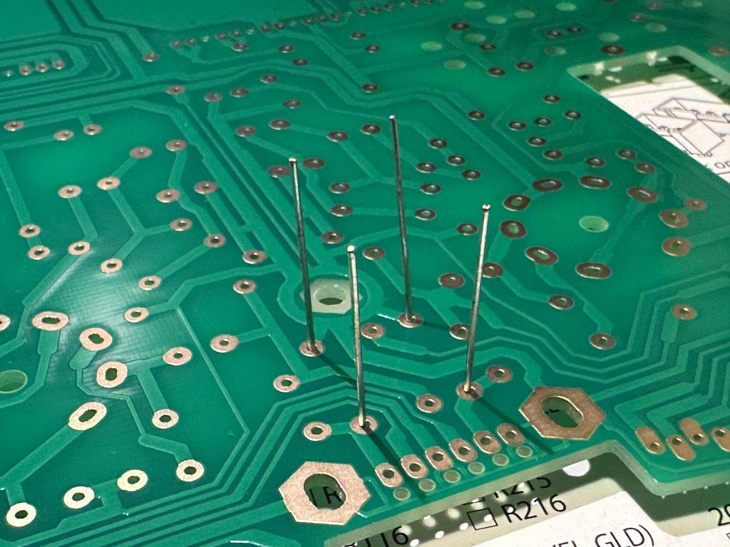
The resistor leads protruding from the other side of the board.
Then, just flip the board over and calmly use the soldering iron. Personally, I’m not a fan of this, but if the resistor keeps falling out after flipping the board, just bend its leads outward from the other side of the board so it doesn’t move. I’m not fond of this solution because if you need to desolder that resistor for any reason (damage, mounting error, whatever), it makes it quite difficult. Untouched leads can be easily worked with a desoldering pump and then you can just remove the resistor. However, if the leads were bent, it sometimes takes much more effort. If you don’t want to bend them either, then… be creative and find your own way to prevent the resistors from falling out.
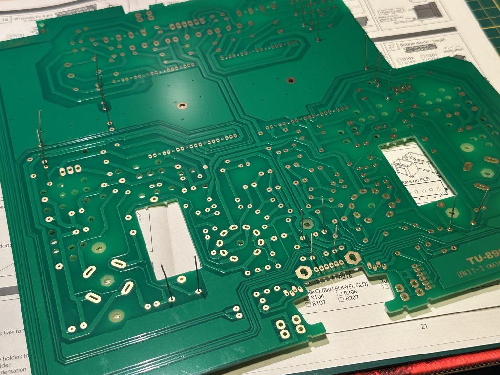
The leads of all the resistors from the first batch are in place.
Are all the resistors inserted? Then, flip the board and solder all the protruding leads. There are 12 resistors, each with two leads, so we should perform 24 soldering operations. You can count them—if at the end there aren’t 24, it means you missed something…
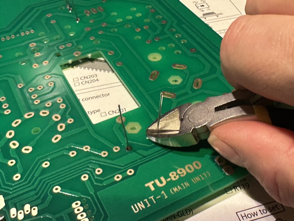
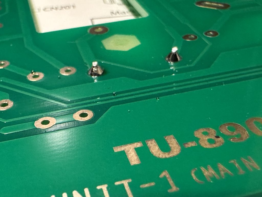
Cutting off resistor ends after soldering
After soldering, cut off the remaining ends with the side pliers, just above the solder – as you can see in the photo. Don’t throw away the cuted off ends, we’ll still need them – collect them somewhere, I use the lid from the rosin box for this purpose.
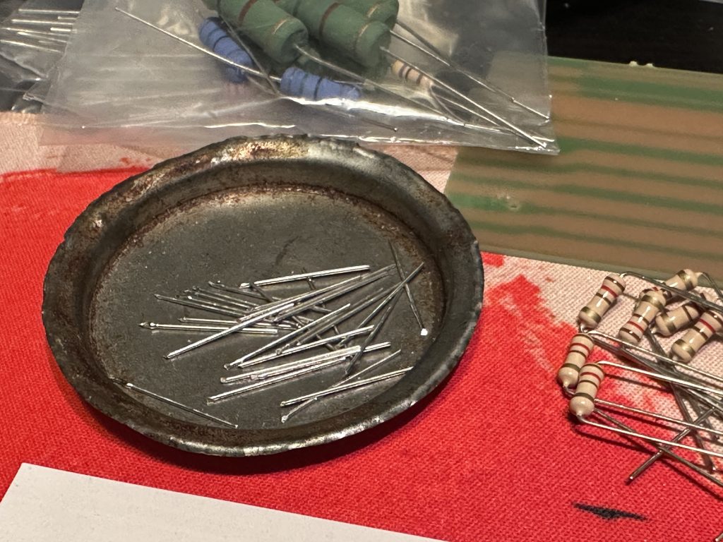
You can collect the cutted ends in a container of some sort – they will still come in handy
The next packet contained resistors colour-coded BROWN-RED-BROWN-GOLD, or 120 Ω. There are to be four on the UNIT-4 board and the remaining six on UNIT-5. So assemble, trim it and took another bag.
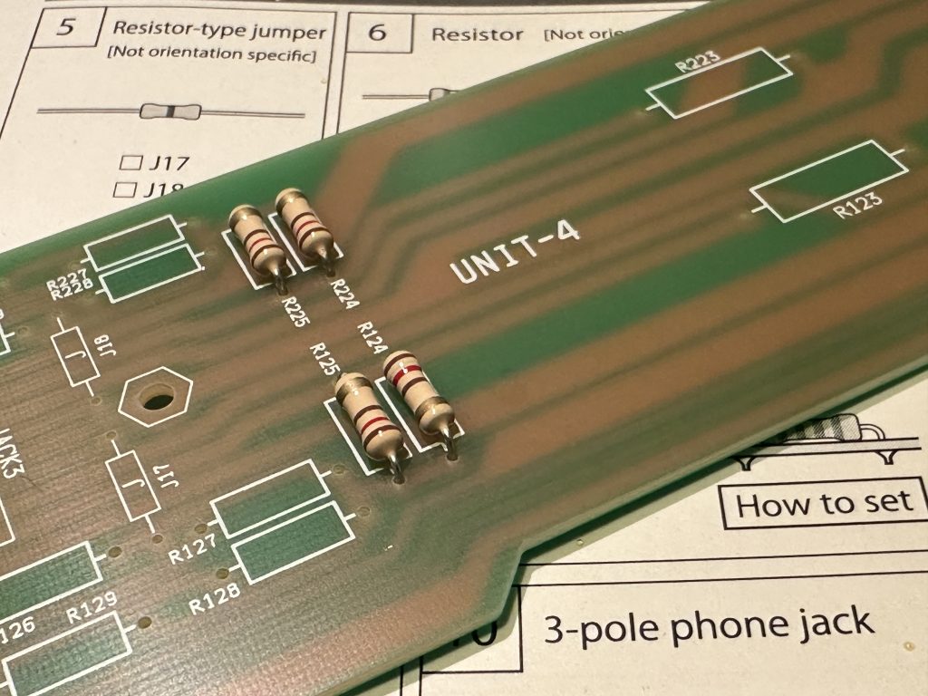
Four resistors on the UNIT-4 board
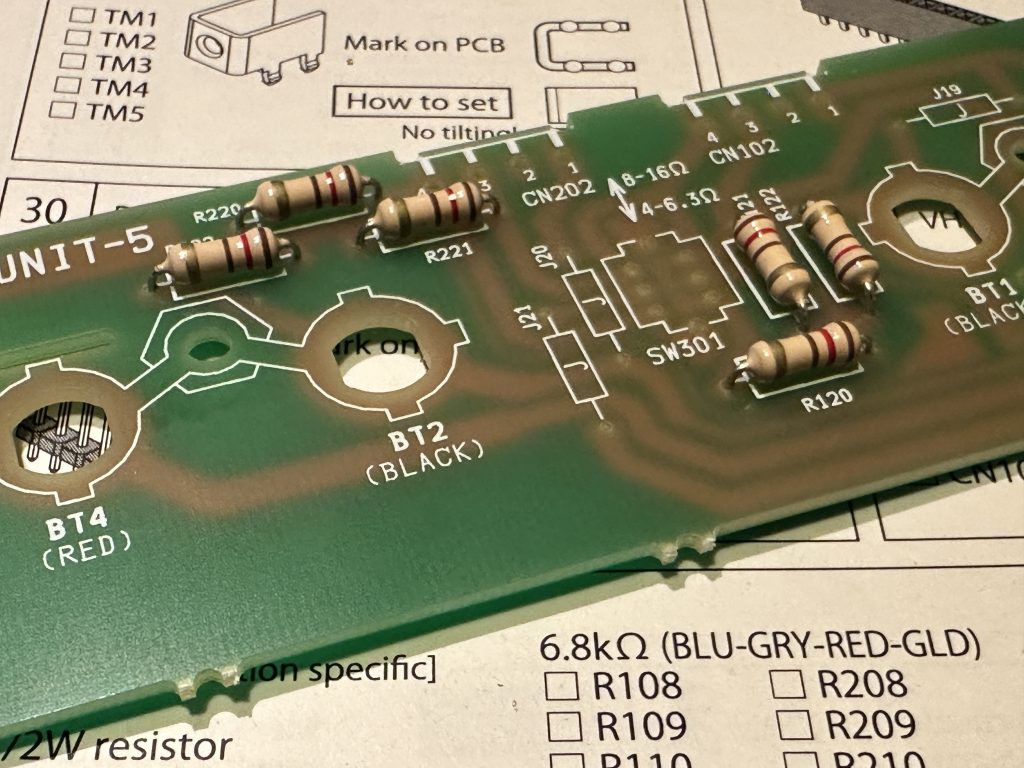
And the remaining six at UNIT-5
The next bag contains resistors of different values – can you see that there are two different sets of coloured strips?
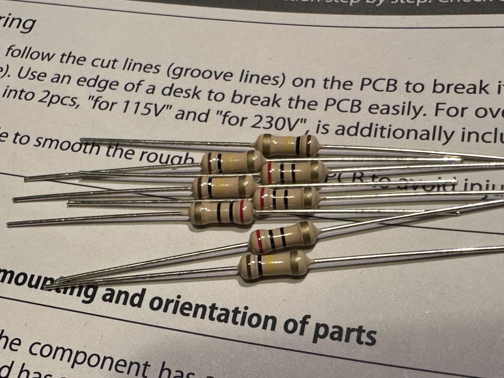
Two different sets of resistors in one bag – this can happen.
We arrange them by colour and find that we have two different values here. RED-BLACK-BLACK-GOLD, or 20 Ω, and BROWN-BLACK-YELLOW-GOLD, or 100 kΩ. If you find resistors of different values in your bag, there is usually a big difference between them – as in this case. Find these values in the lists (you will find them at UNIT-4 and UNIT-1) and assemble.
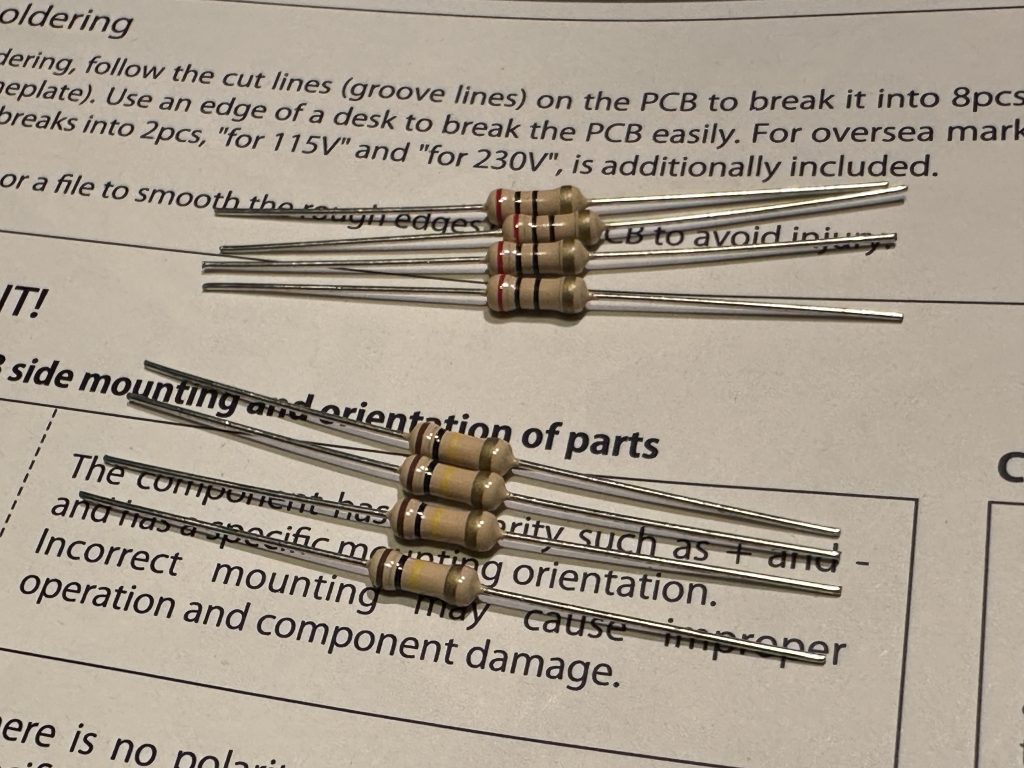
Resistors from the following packet
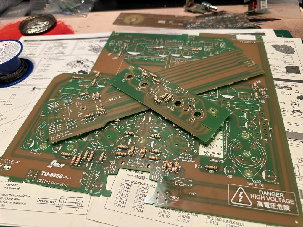
PCBs with resistors installed so far
Take another bag, which have eight pieces in it with BROWN-GREEN-ORANGE-GOLD colours, that is 15 kΩ, check it with a meter – 14.7 kΩ, within tolerance.
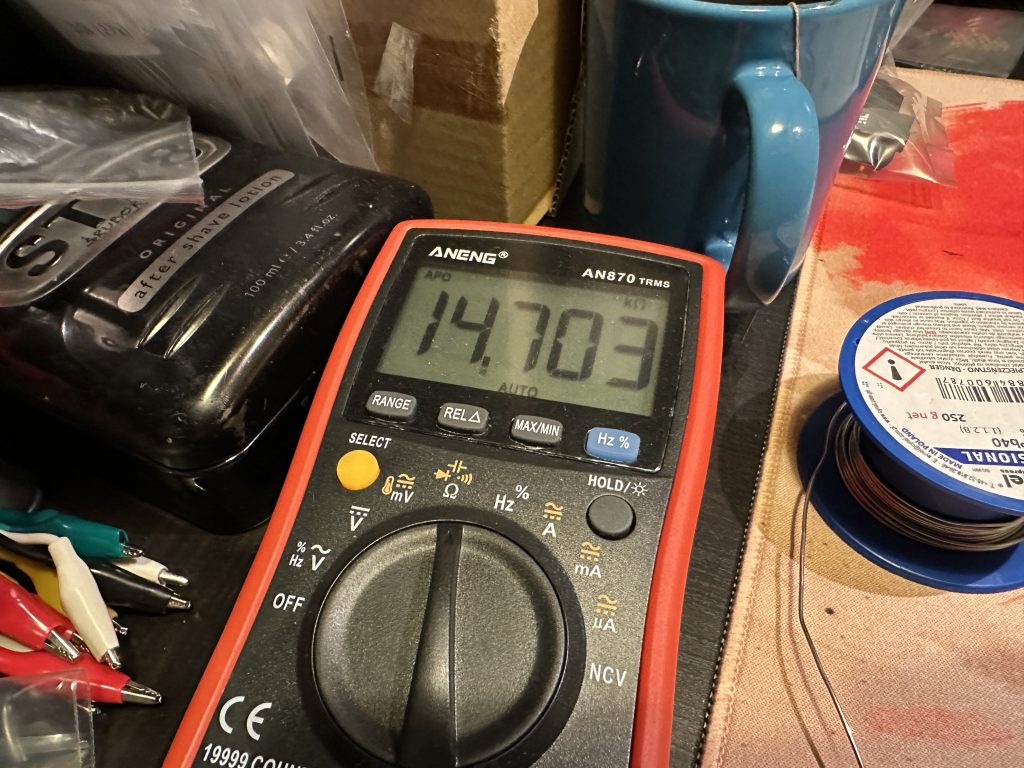
Measuring the value of the following resistor, it is within tolerance
As can be seen in the image below, all eight 15 kΩ resistors should be mounted on the UNIT-1 board.
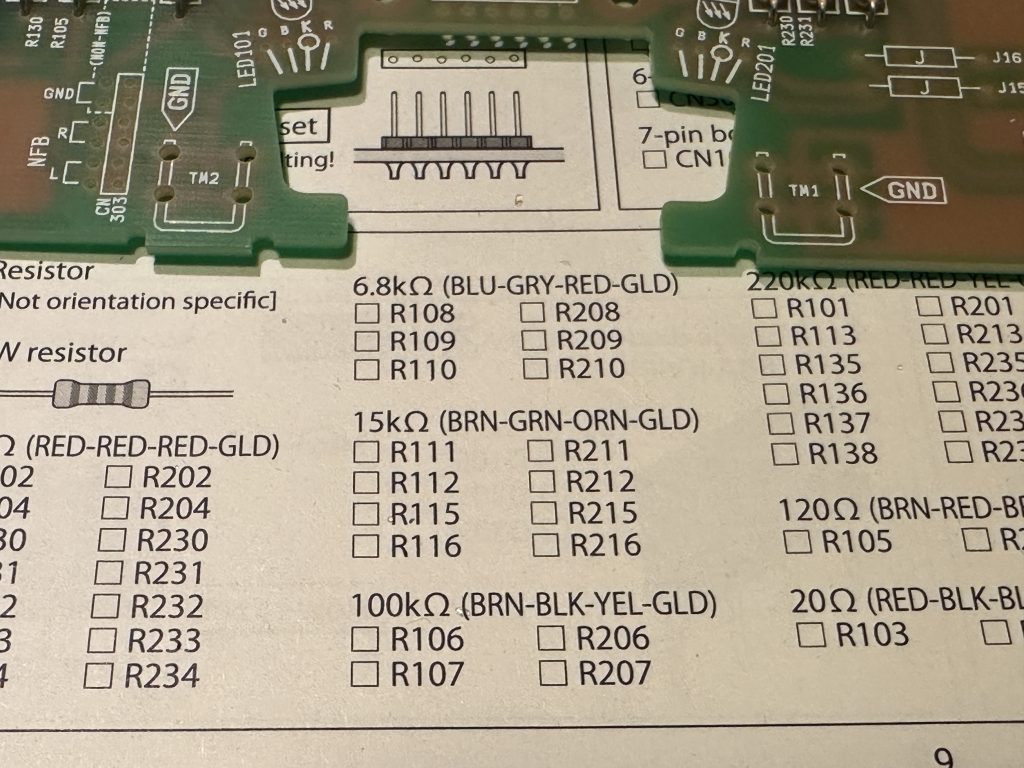
Mounting list of 15 kΩ resistors
I think that after going through these three examples, the rest of the resistors shouldn’t be a challenge for you anymore. So let’s grab the next bags and keep installing the resistors as per the instructions.
But there’s one special case we need to talk about. At some point, you’re definitely going to come across a bag with 21 “resistors” that either have a single black stripe in the middle or no markings at all. These aren’t actual resistors — they’re jumper wires made to look like resistors. Their resistance should ideally be zero, just like with any proper jumper. If you measure them with a multimeter, you might get a reading like 0.2 ohms. Not quite zero, but is that a problem? Nope — you can safely install them. What the multimeter is really showing isn’t just the jumper’s resistance, but also the resistance of the test leads. This happens in every measurement, but we usually ignore it when we’re dealing with higher resistance values — for example, a 0.2 ohm offset on a 100 kohm resistor is basically nothing. But when you’re dealing with very low resistances, like jumpers, it actually matters.
Ideally, you should first measure the resistance of your test leads alone, then measure the jumper, and subtract the lead resistance from that reading. That’s how you get the actual resistance of the jumper itself. But how do you measure lead resistance? I’ll leave that as homework for those who don’t know yet 😉 I already know that my meter’s leads add about 0.2 ohms — so when I see that number, I know the jumper is perfectly fine.
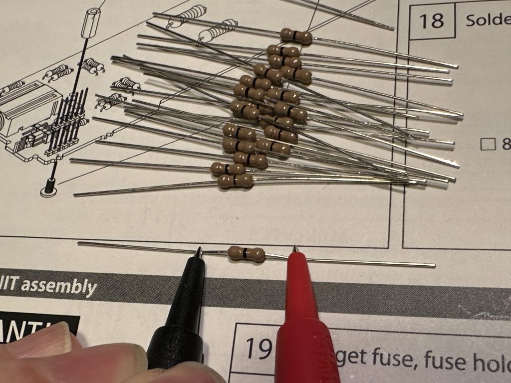
Jumper resistance measurement
Alright, but why do these jumpers look like resistors? Couldn’t we just solder in a piece of wire instead? Like, say, leftovers from resistor leads we’ve already cut off? Of course we could — that would be fine. But using these resistor-shaped jumpers is usually easier and more convenient. You just bend the leads and drop them in, instead of fiddling with cutting wire to the right length and shaping it. Also, this kind of jumper is often used in automated assembly. The machines are already optimized for placing resistors, so to them, a jumper that looks like a resistor is just another standard part — it gets placed and soldered the same way as any other.
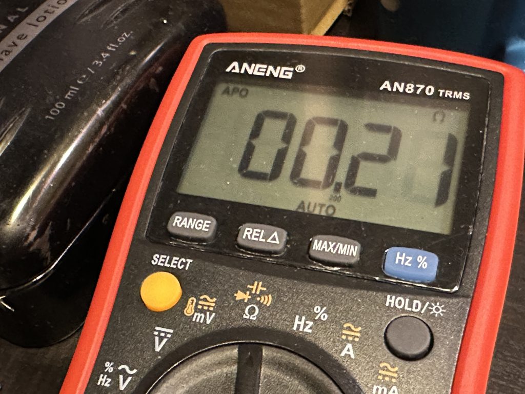
The result of the jumper resistance measurement – it is actually the sum of the resistance of the jumper and the test leads.
You should have no trouble installing the remaining low-power resistors — just remember, if you can’t find where a resistor is supposed to go… keep looking. It’s definitely there. And if you end up with a leftover resistor, it means you probably forgot to install one somewhere. On the other hand, if you’re missing a resistor — well, it’s probably on the floor. Or hiding under the assembly manual. In all my experience, I’ve never had a kit with missing or extra resistors (okay, sometimes you get a few extra screws or nuts, but that’s about it 🙂).
At the end, we install the higher-power resistors — the process is the same as with the smaller ones. The only thing to keep in mind is: don’t push them all the way down to the PCB. It’s better to leave a small gap — around 1 or 2 millimeters — between the resistor and the board to allow for better airflow. These resistors can get noticeably hotter during operation, so let’s give them a bit of breathing room to help with cooling. You might also notice that the PCB under and around the biggest resistors has extra holes — that’s exactly what they’re for: improved heat dissipation.
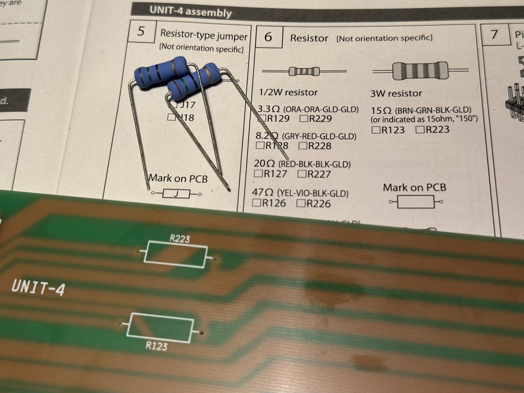
3 W resistors
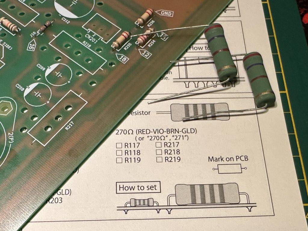
5 W resistors
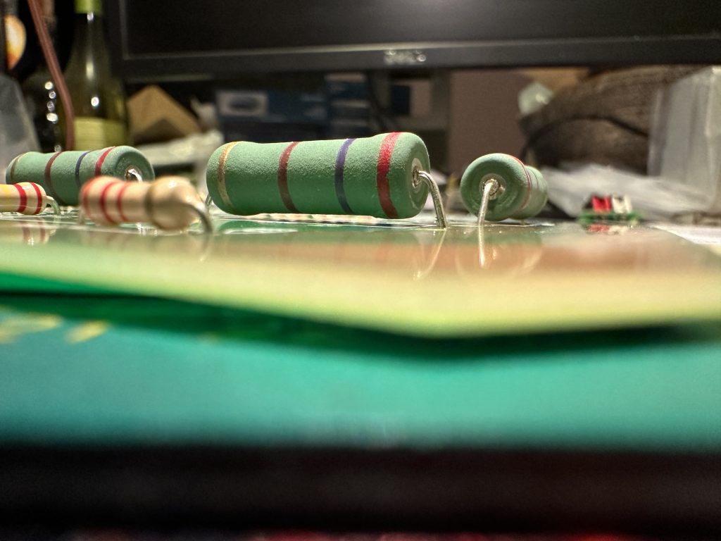
Gap between power resistor and PCB. Could be larger.
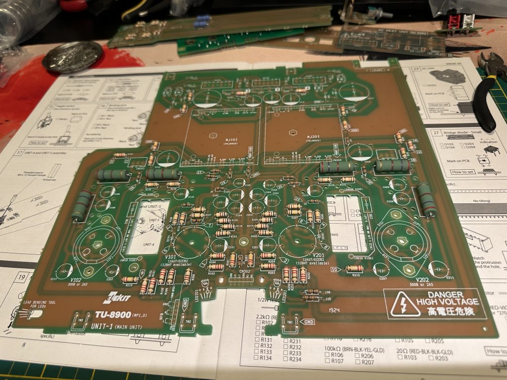
UNIT-1 board with all resistors installed
Once you’re done installing all the resistors, go back to the assembly sequence in the manual. Now it’s time for the UNIT-4 board, step 7 — installing the pins for the jumpers that set the headphone volume level. When inserting the pin headers, make sure their plastic housing sits perpendicular to the PCB. The longer ends of the pins should face the front of the board, while the shorter ends go into the PCB.
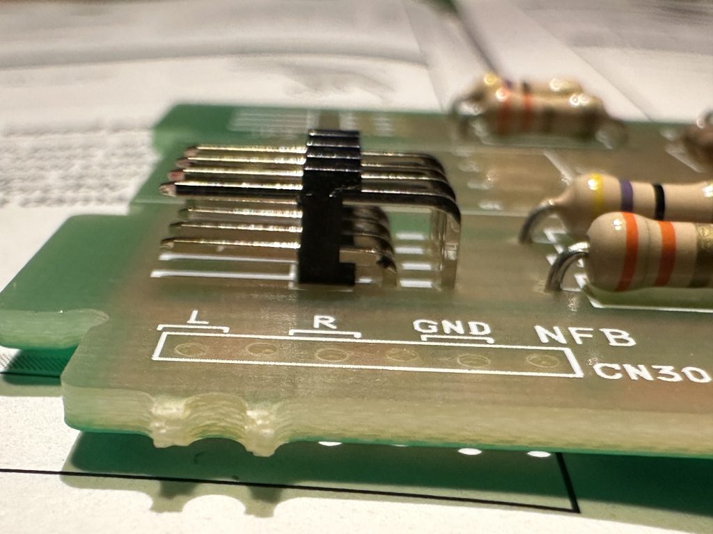
Pins to set headphone volume
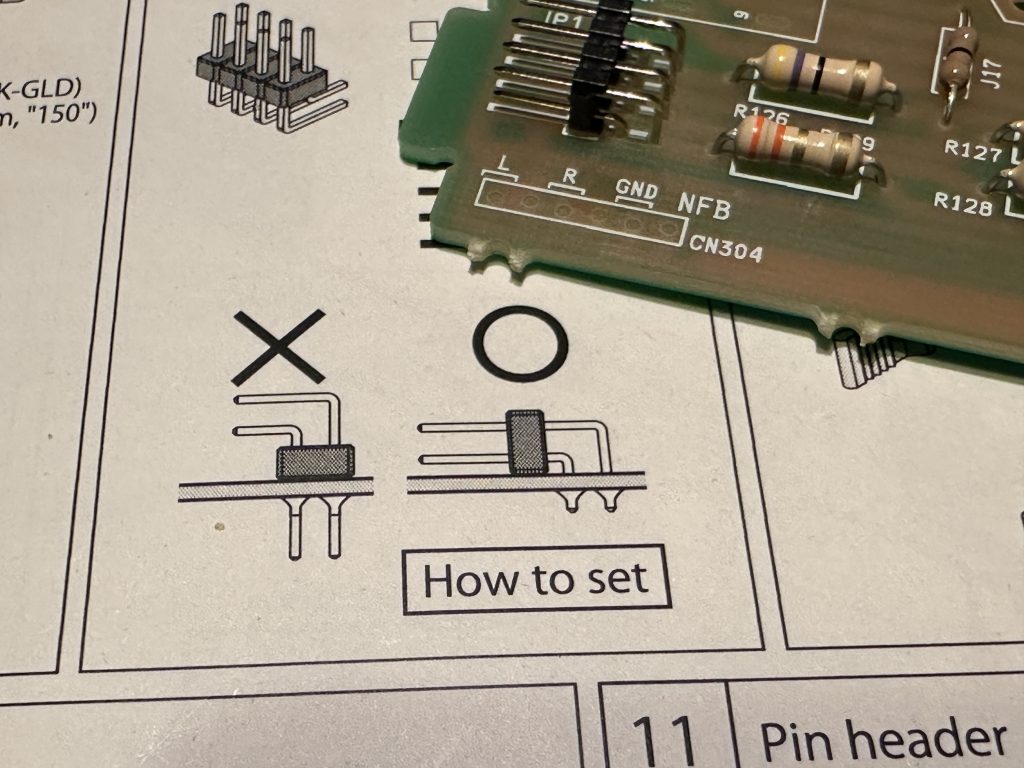
Longer tips forward, shorter tips enter the plate.
You’ll find the jumpers for those pins in one of the bags. They’re yellow, so it’s pretty hard to miss them. But there’s no need to go hunting for them right now — when you eventually come across them, just come back to this spot and pop them on any way you like. You’ll find out at the very end of the build how they’re supposed to be set.
Next up is a metal mounting part with a threaded hole. As shown, it should go into the four holes with the flat side — the one with the threaded hole — facing outward from the board. As always, press it in firmly and double-check that it’s oriented correctly, just like in the photo.
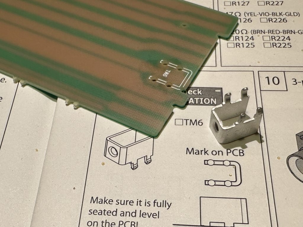
Clamping element
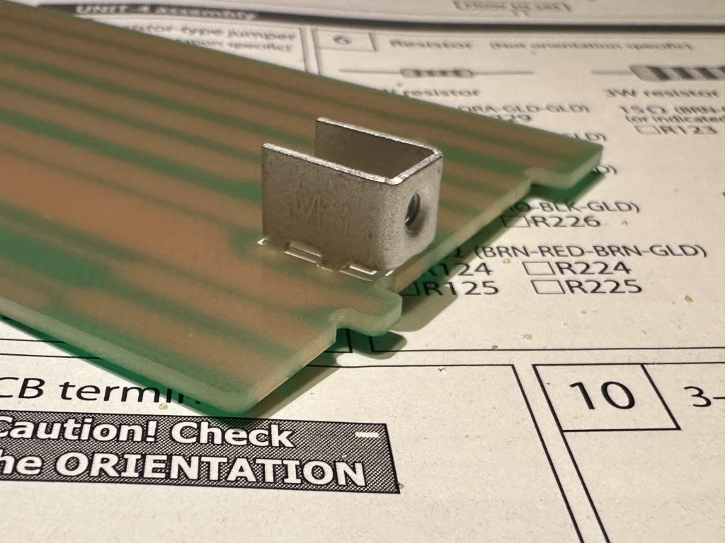
Push it well against the surface of the plate – with the flat part with the threaded hole outwards
Solder it like any other component, but keep in mind that since it’s relatively large, it might take a bit longer for the soldering iron to heat it up properly. Be careful during this step — it’s going to get really hot.
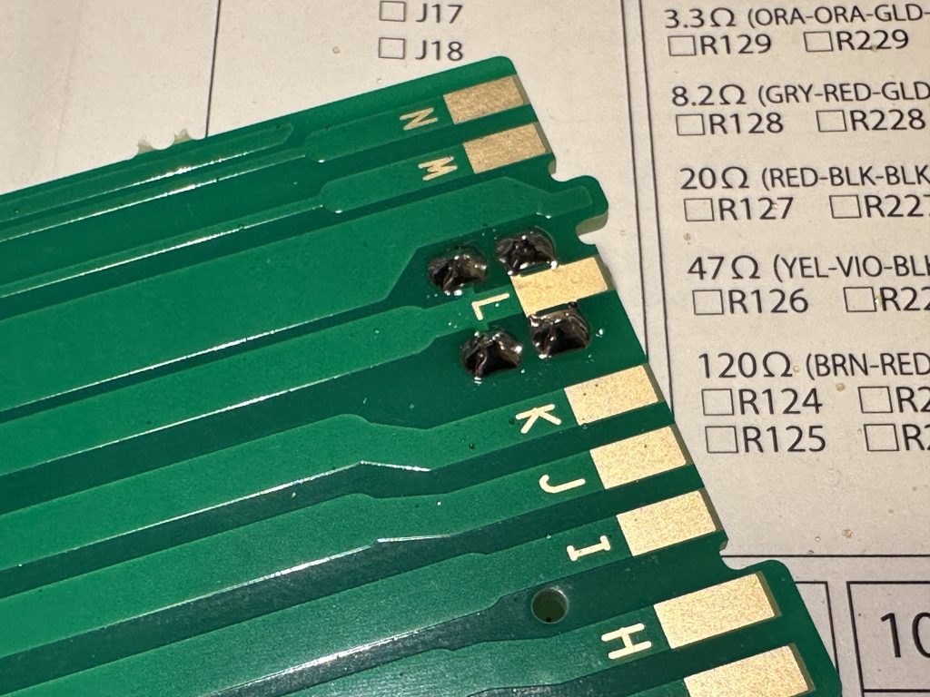
Soldering the assembly element
Step 10 is the headphone jack. As always, make sure to press it firmly into the board, and before soldering its pins, double-check that it’s seated correctly.
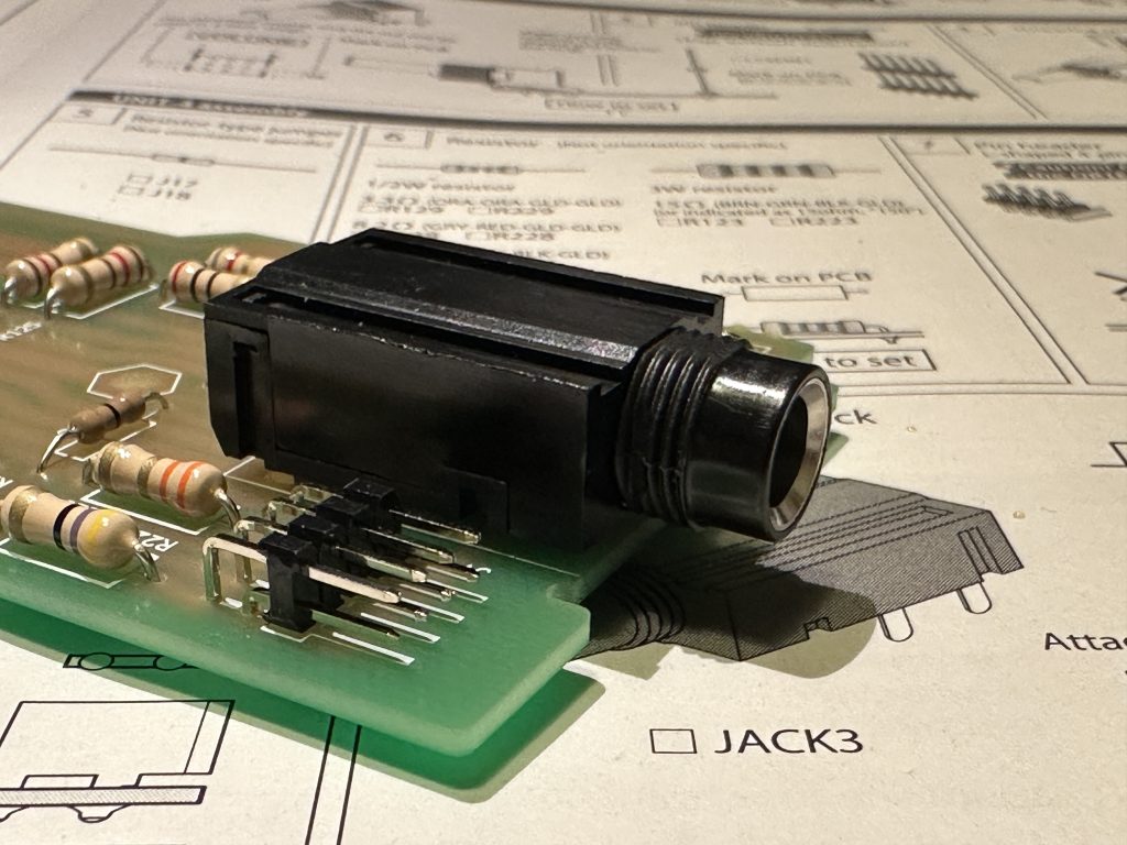
Installation of headphone socket
The last component on this board is the goldpin header — you’ve already soldered a similar one on the potentiometer board.
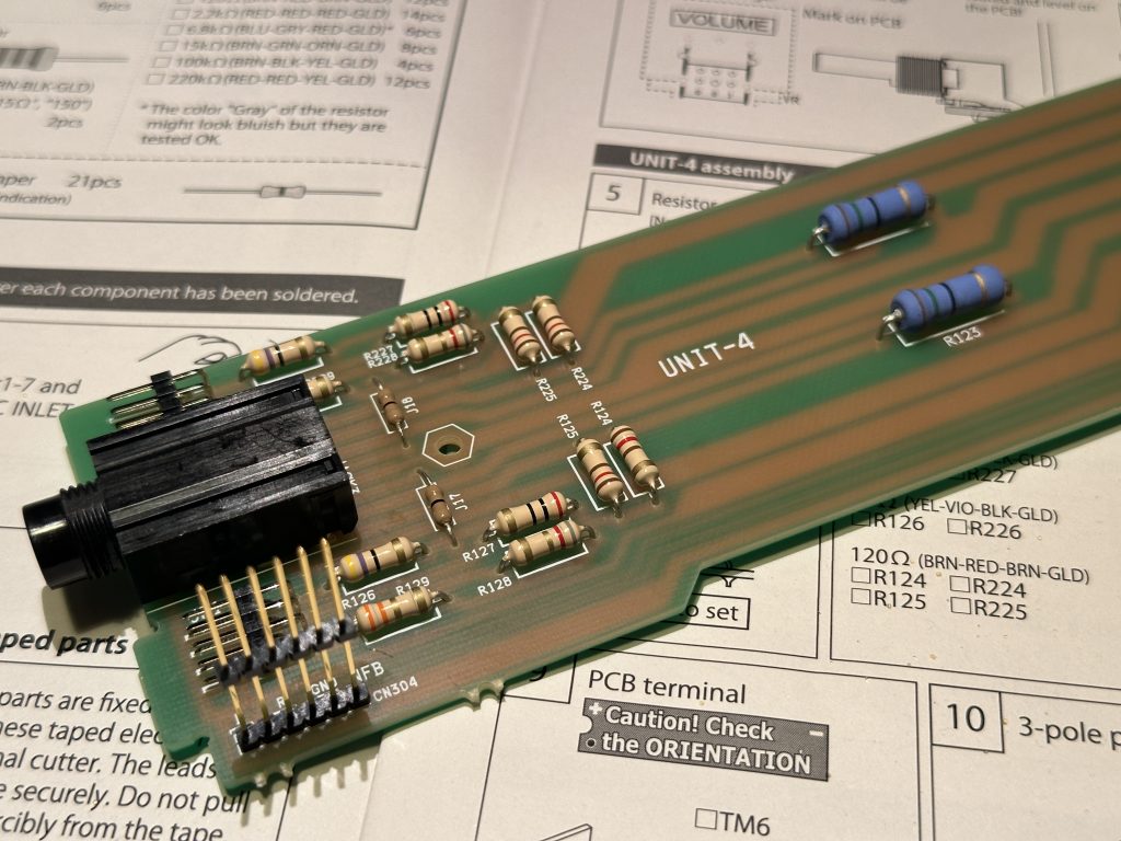
Goldpin ladder – the last element on the UNIT-4 board
Set the assembled UNIT-4 board aside — now we’re moving on to the next one. According to the manual, that’s UNIT-5, the board with the speaker connectors.
The first step after the resistors we installed earlier is step 14 — two edge connectors. The drawings in the manual are very clear, so there shouldn’t be any issues with this. The connectors don’t need to be mounted perfectly straight, as they’ll be used to plug in the connectors with wires from the speaker transformers.
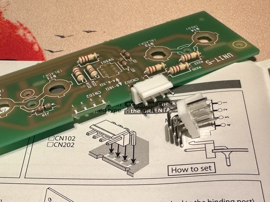
Edge connectors
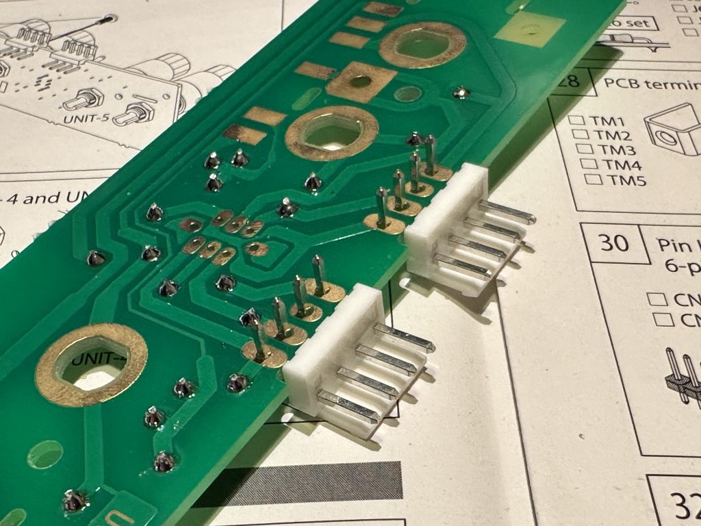
Preparation for soldering connectors
The UNIT-5 board also has a speaker impedance switch. Once again, make sure to press it firmly into the board and check its alignment before soldering.
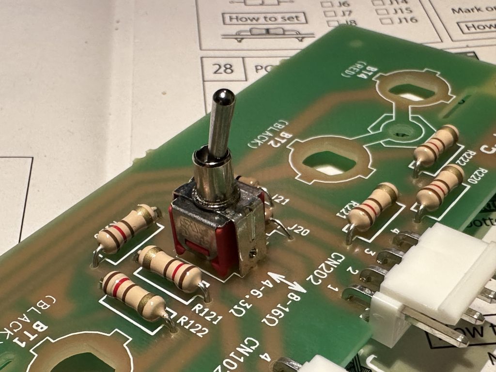
Speaker impedance switch
The speaker connectors aren’t soldered, they’re screwed in. Start by unscrewing and removing both nuts from each connector. Leave the plastic red and black washers on the connector.
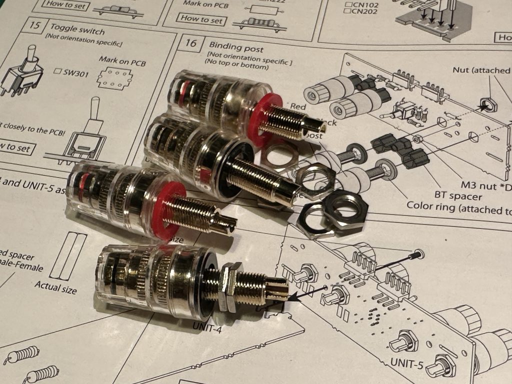
Loudspeaker sockets – remove the nuts from them
For the assembly, we’ll need plastic spacers and two M3 nuts.
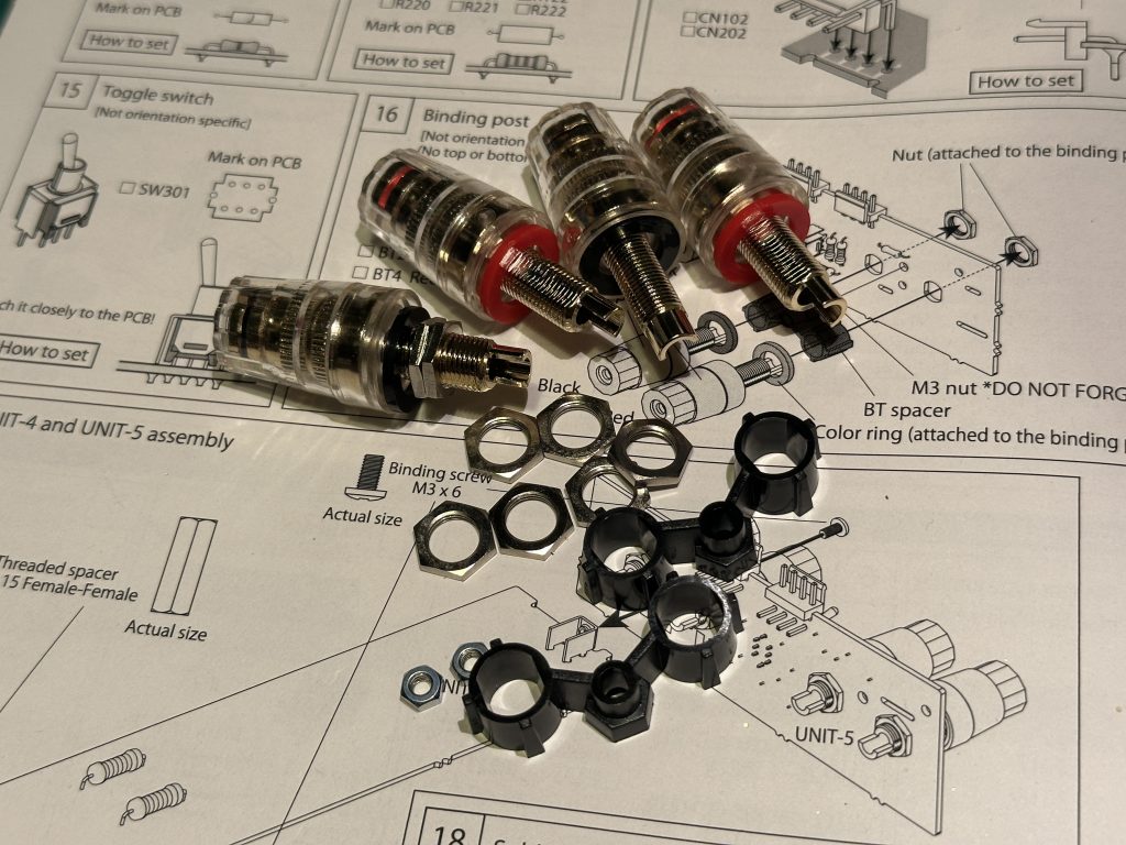
Set of components for fitting headphone sockets
The nuts are placed in the hexagonal holes of the spacers.
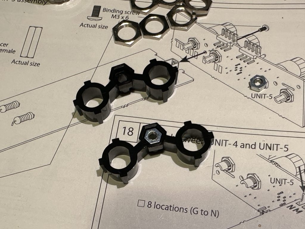
Remember to put the nuts in the spacers
To make your job easier, set up the connectors with the spacers in place and the PCB board as shown in the picture below. Pay attention to the colors of the connectors — they must match the labels on the board. The position of the notch on the connector end doesn’t matter.
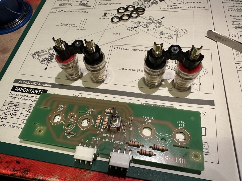
Installation aids
Now, flip the board over and place it onto the connectors. Note that the holes in the board and the spacers aren’t round, but slightly flattened — just like the end of the connector. Secure each connector with one nut, tightening it firmly, but of course, be careful not to crack the board.
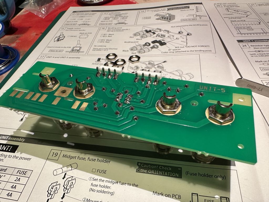
The sockets are screwed on the other side of the board
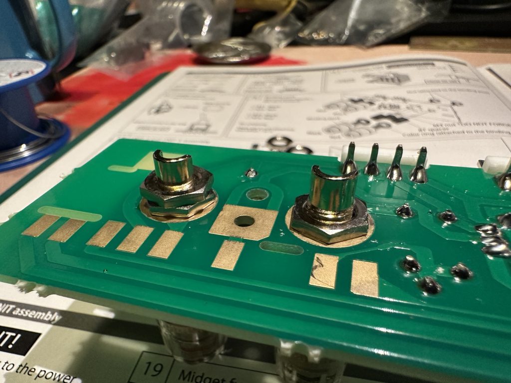
The nuts can be counteracted
There’s no need to screw on the second nut, but it’s a good idea to do so — this way, you’ll lock the first one in place and prevent it from loosening.
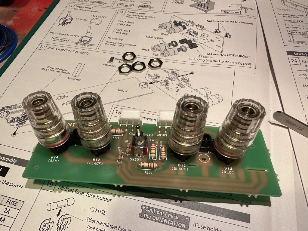
UNIT-5 finished module
Now we’ll connect the UNIT-4 and UNIT-5 boards into one larger module. But first, we need to install a metal spacer bushing on UNIT-4, securing it to the board from the bottom with an M3 screw.
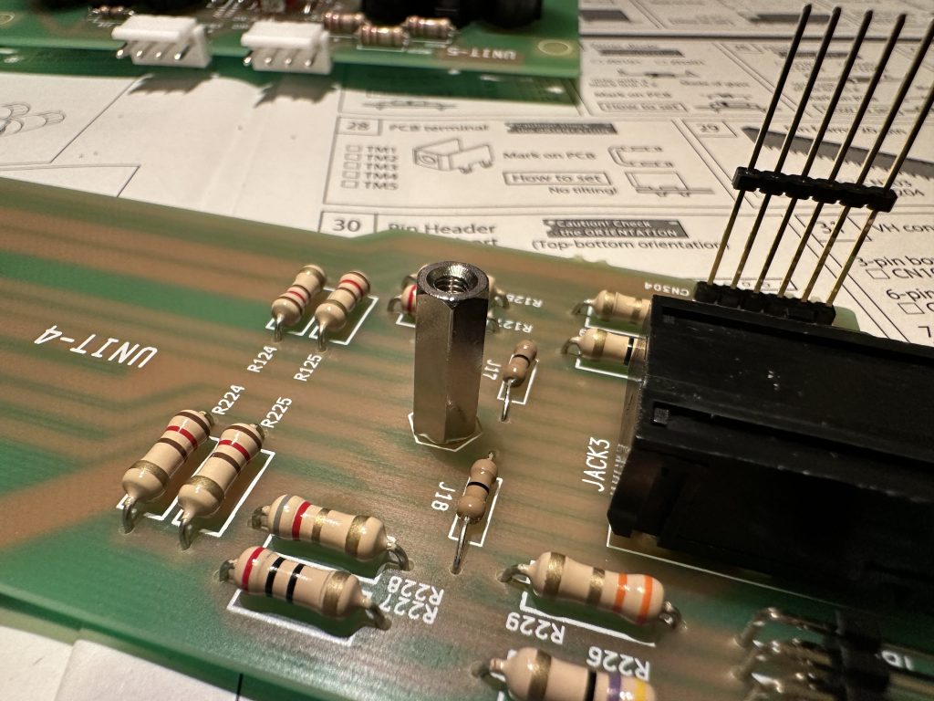
Spacer sleeve on UNIT-4 plate
Next, insert the UNIT-4 board into the corresponding cutouts on the UNIT-5 board and screw the two boards together with an M3 screw. Make sure the UNIT-4 board is aligned properly with the UNIT-5 board.
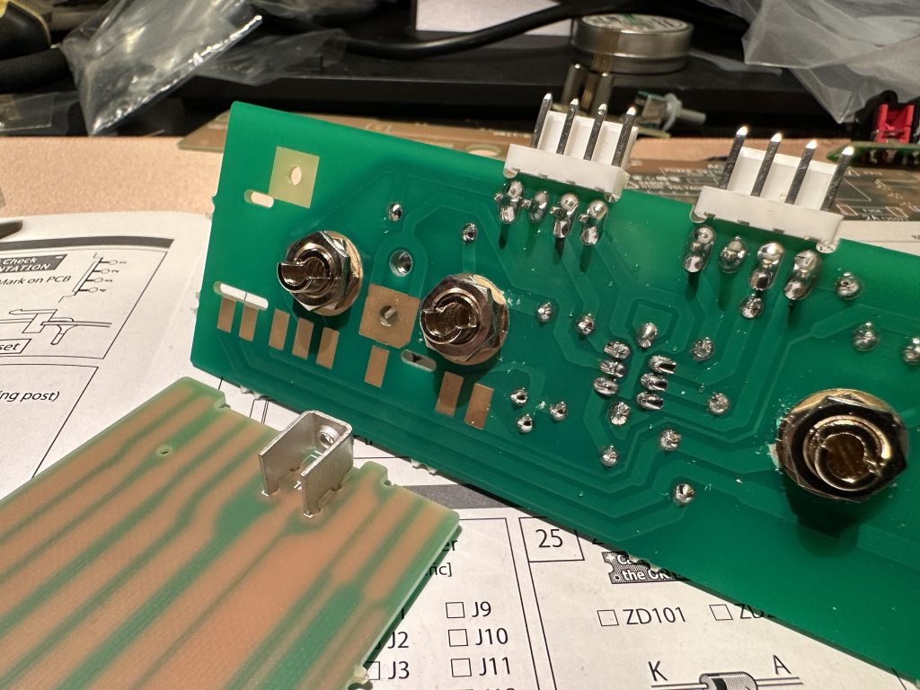
Mechanical connection of UNIT-4 and UNIT-5 boards
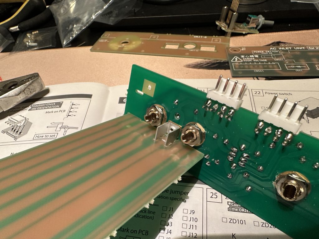
The tiles should be screwed together
Flip the assembled boards over and solder all the trace connections from G to N, eight pads in total. If you try to position the boards as shown in the picture, it will be easier to solder the connections — the molten solder will naturally flow into the recesses and settle in place.
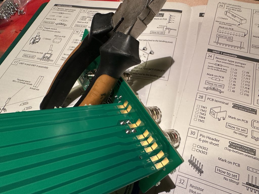
Convenient soldering of connected boards
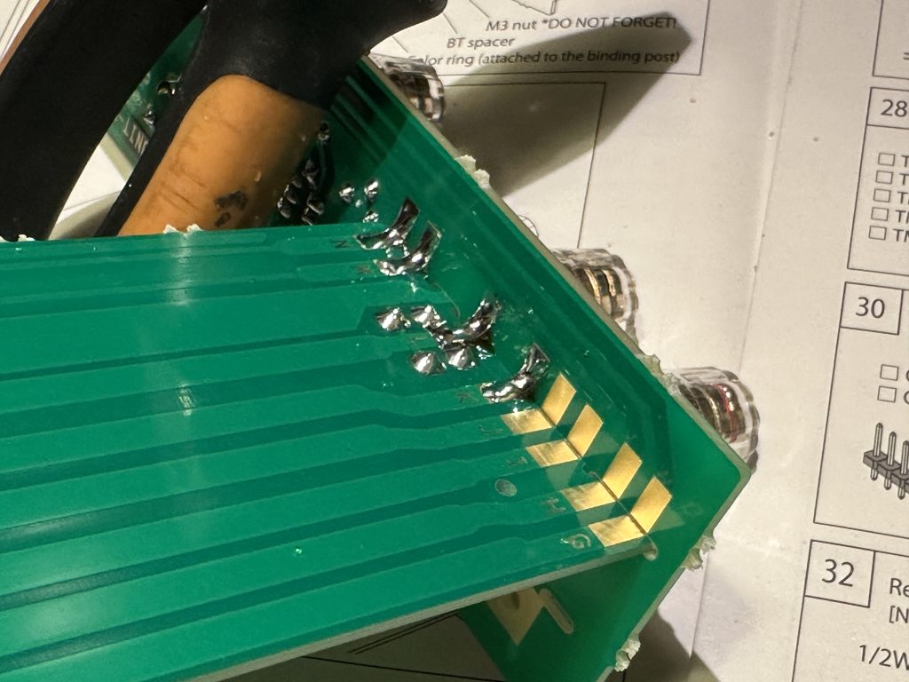
Soldering of all connections between boards
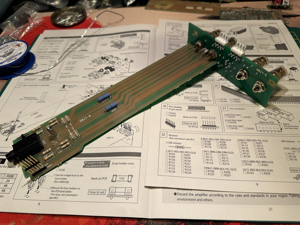
Finished module from UNIT-4 and UNIT-5 boards
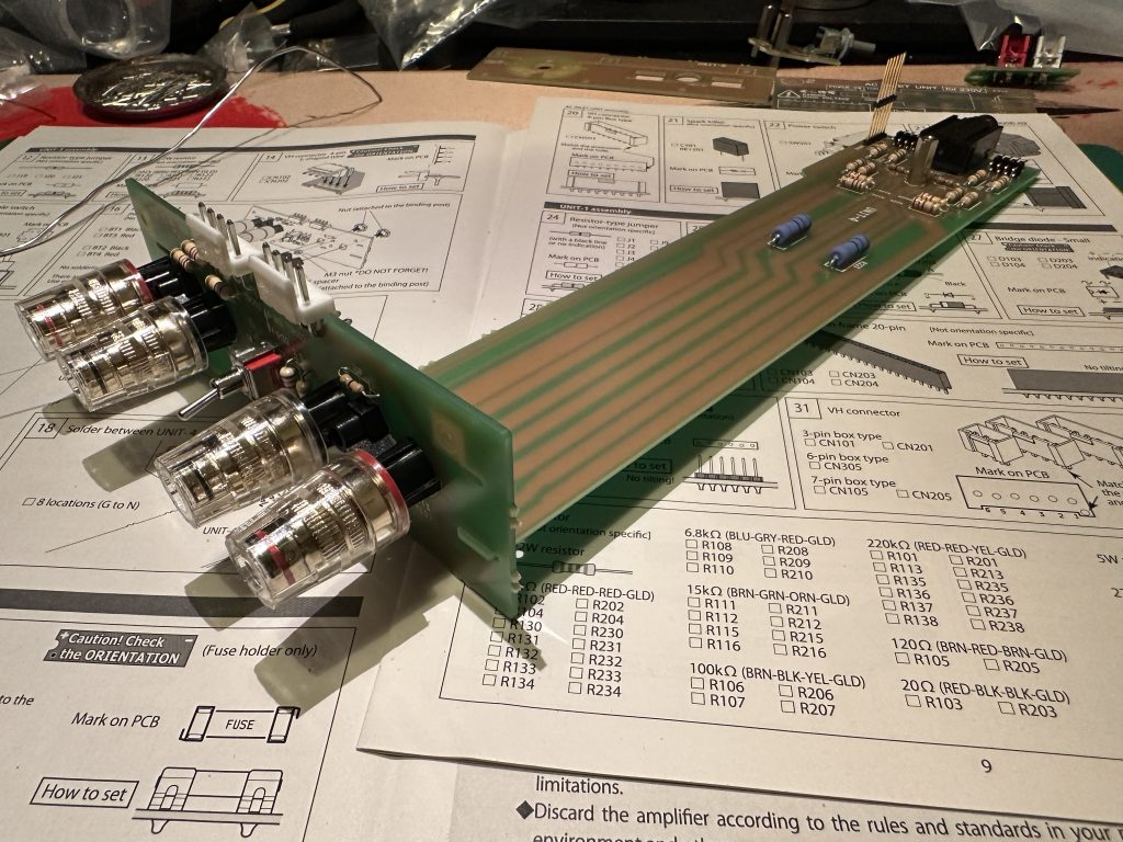
Finished module from UNIT-4 and UNIT-5 boards
The finished module, with the connected and soldered UNIT-4 and UNIT-5 boards, can be set aside — we’ll come back to it during the final assembly.

You must be logged in to post a comment.