ELEKIT TU-8900 or how to build a tube amplifier – part 1
Tube technology is a bit of a forgotten world now, although many people still remember the televisions and radios that worked thanks to those glowing tubes. The invention of the transistor changed electronics irrevocably, but even though they have huge advantages over tubes, for those who value high-quality sound, tube amplifiers are still a highly desirable part of their home system. And this is not just snobbery or nostalgia, suffice to say that now, in the 21st century, the amplifiers most valued for their sound quality are precisely tube designs. It’s not for nothing that many world-famous guitarists use such amplifiers exclusively. And quite seriously, if you get the chance to hear what high-quality recordings reproduced with a good tube amplifier sound like, you will find it quite difficult to part with it. Unless, of course, an elephant was stepped on your ear 😉
For many years now, the Japanese company Elekit has been offering excellent quality tube amplifier kits for self-assembly. Their designer is Mr. Fujita, whose designs have gained great popularity, both among enthusiasts of high quality sound and among electronics hobbyists, for whom building such an amplifier by themselves is also an interesting experience and often a dream come true. Often they then become audiophiles too 🙂
However, there is a large group of people who, although they would like to build such an amplifier, are worried about whether they are up to the task. After all, it is quite a challenge, and on top of that, the tubes require dangerously high voltages to work and they still heat up…. For all of these, we have prepared this report on the assembly of the currently highest model of the Elekit TU-8900 amplifier. The amplifier is based on two ECC82 tubes in the voltage gain stage and directly heated 300B power triodes – incidentally, among audiophiles, these are one of the ‘cult’ tubes, highly appreciated for the quality of the sound produced. The kit is available in two versions: TU-8900E – which features standard output transformers, and TU-8900VK – which features the highest quality, handmade transformers from the highly regarded Swedish company Lundahl. And this is the only (but significant) difference between the versions. We will assemble the basic version, which in time can also be fitted with Lundahl transformers, if we have the desire and financial resources to do so, because there is no denying that top quality costs money. At the same time, it should be made clear here that all the original components from the kit, including the transformers, are of really good quality and there is absolutely no need to change them straight away, although, of course, there is always room for improvement 🙂
The kit we will be assembling, contains almost all the components you need to build a working amplifier – resistors, capacitors, PCBs, active components and, of course, the chassis. Only the tubes are missing from the basic version – however, you can order the kit straight away with tubes. At the moment we offer tubes from the new production of the Slovakian company JJ Electronic, but of course you can use any other tubes. You will also need a power cable to run the unit – the kit contains such a cable, but it is terminated with an original Japanese plug, which unfortunately does not fit into our sockets. You can change this plug to our European plug yourself, or use other standard IEC-type mains cable.
Why don’t we add European mains cables to the kits?
On the one hand, the IEC mains cable is a relatively simple product, which can easily be purchased at any electronics shop and, by the way, the necessary length, the appropriate plug etc. can be selected. On the other hand, it is not uncommon for audiophiles to use dedicated mains cables with special plugs and sockets anyway, and such a standard cable lands immediately in the bin. For this reason, we have decided to leave the original Japanese mains cable as it is and leave it up to the user to decide its further fate.
Can I build a tube amplifier too?
I’ll put it this way – if you know how to solder, have at least a general understanding of electronics (i.e., you can tell a resistor from a capacitor), possess some basic technical aptitude, and aren’t afraid of a screwdriver or pliers – then you’ll manage just fine 🙂 The key skill here is soldering – everything else is so well explained in the assembly manual that you just need to follow the instructions carefully. The manual is in English, so knowing the language would be helpful, but it’s also very visual, so it’s by no means essential. You could even work with the original Japanese manual without much trouble if you felt like it.
I hope this assembly report will show you that it really isn’t all that difficult. I’ve assembled at least a hundred different Elekit amplifier models by now, and so far, I’ve only had one case where the device didn’t work right after assembly. But that happens if you forget to solder a few leads… It’s a similar story for people who aren’t electronics professionals – the only cases of issues assembling the kit were due to assembly errors. Either a part was omitted, installed backwards, or the wrong type of solder was used…
However, even though it’s not terribly difficult, I must warn you for your own safety – a working amplifier contains high voltages that can be life-threatening, so you should NEVER tamper with it while it’s powered on! Even after switching it off and unplugging it from the power supply, you must wait a few moments for the capacitors inside the amplifier to discharge before doing anything inside. Additionally, the tubes (valves) heat up to high temperatures during operation and can cause serious burns. They are also made of glass and contain a vacuum inside, so breaking one can also be dangerous.
To sum up, if you:
- know how to solder,
- can handle a screwdriver and know the difference between a screw and a bolt,
- aren’t afraid,
- and most importantly, want to do it,
and if you:
- don’t rush,
- follow the instructions carefully,
- and don’t mess with the amplifier while it’s powered on,
then you can build this kit. And any other Elekit kit too 🙂
Getting Ready
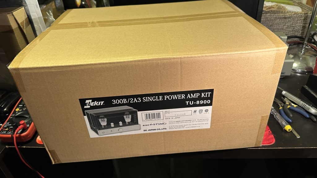
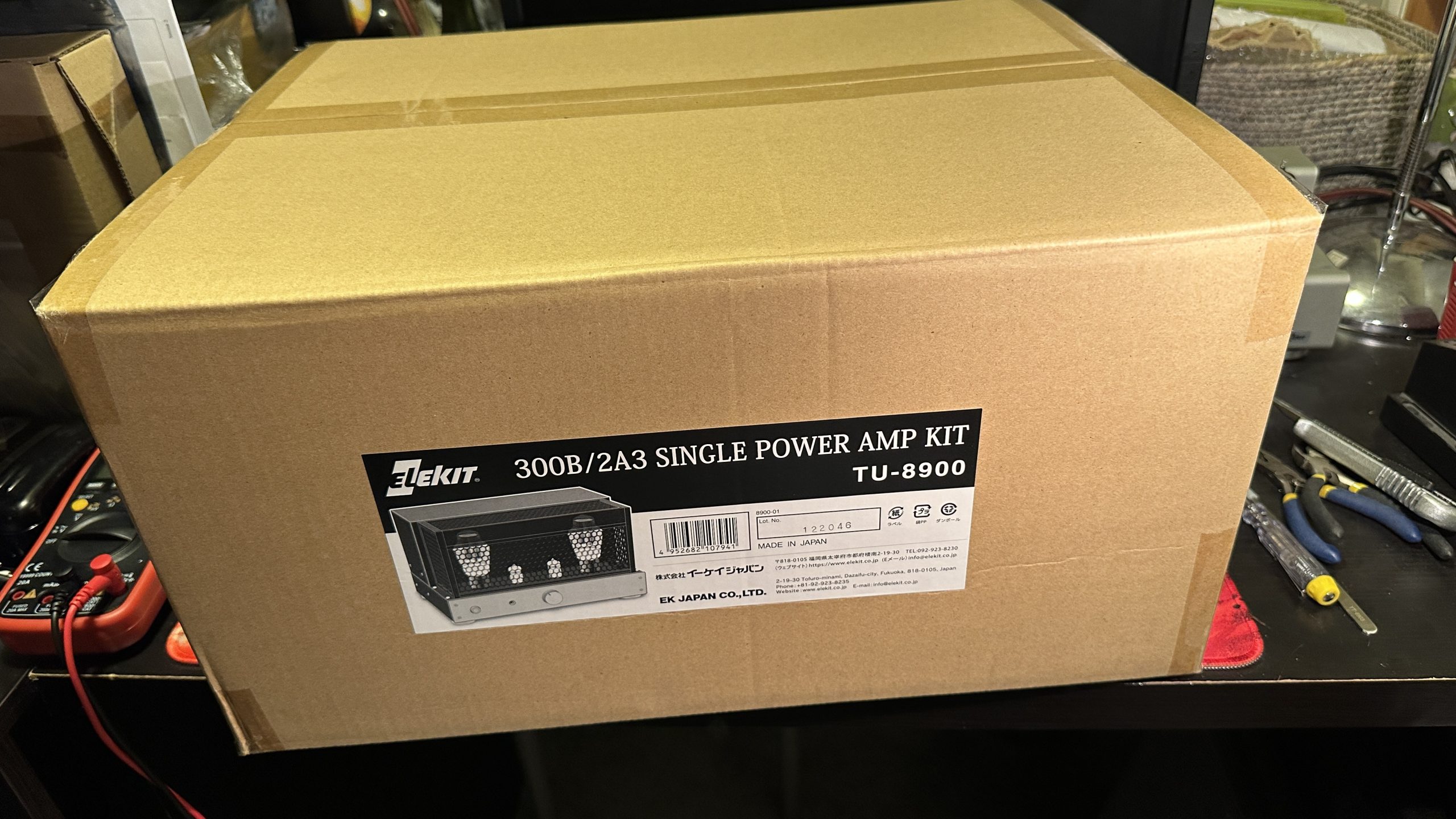
The kit comes in a fairly large and heavy box – after all, it has to fit the enclosure, which has some weight to it, and the transformers aren’t exactly the lightest components either.
We open the box and take out the manual, the PCB, and all the bags of components. The power transformer is tucked away in the top left corner of the box – we can leave it there for now. The output transformers are in the bottom right corner, under the component bags. We won’t need those until later either, so they can stay in the box for now, along with the case, which is additionally wrapped in protective paper.
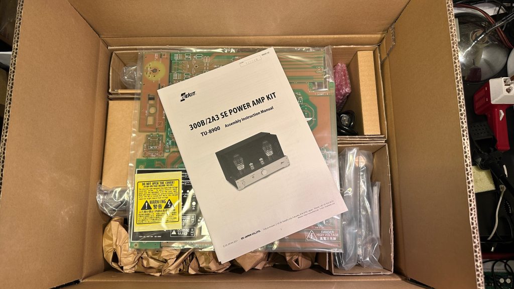
The kit box right after unpacking
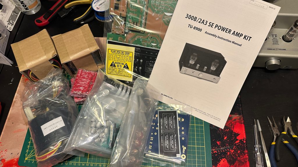
The individual components of the kit taken out of the box
Tools
A few tools will be needed for the assembly. The most important of these is, of course, the soldering iron. Virtually any soldering iron will do, but the best choice is a heated type with at least 35W of power. You’ll also need a tip cleaner, solder, flux, a Phillips screwdriver, side cutters for trimming component leads, and small flat pliers. A knife and scissors will also come in handy. The multimeter shown in the picture below isn’t essential, but it makes the job easier, especially when identifying resistors marked with colored bands. I must admit, I’m not particularly fond of this, mainly because sometimes it’s hard to tell one color from another. It’s faster to just measure the resistor’s value. However, if you don’t have a multimeter, it’s not a problem – you can successfully work without it. You can find a description of how resistor values are coded with colored bands on, for example, Wikipedia.
I need to add a few words about solder. Buy regular, known brand leaded solder (e.g., SnPb from the Polish company Cynel :)), a small 100g spool will be enough. Absolutely do not buy and do not use lead-free solder or the “special” audiophile solder with added silver or gold. The reason is simple – soldering with these types of solders requires a lot of experience and is an order of magnitude more difficult than using regular solder. There’s a high chance that even if the joints look correct, they will either be “cold” solder joints and the amplifier won’t work, or after a short period of use, problems will arise due to cracking and non-conducting connections. And I can bet that you WON’T hear a difference in the performance of an amplifier soldered with regular solder compared to one soldered with silver-added solder. But you will definitely notice the difference in your wallet.
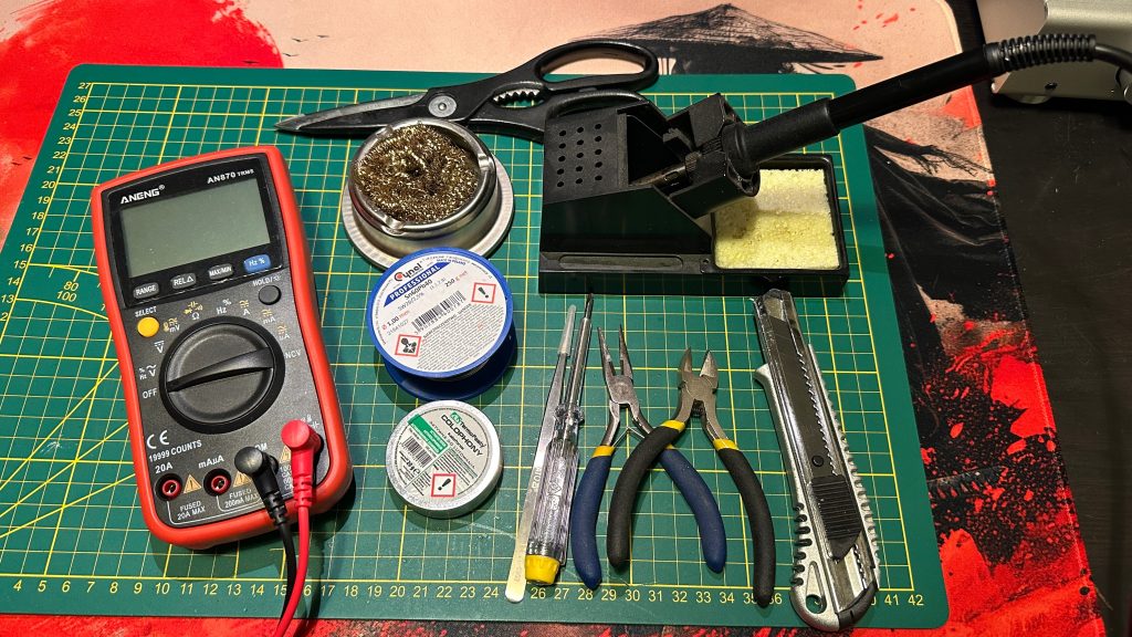
A set of essential and useful tools used during assembly.
PCBs plates
The amplifier is built using a few PCB boards, where we’ll be installing the components using through-hole technology. So, the first step is to get those boards ready. In the kit, you’ll find one large board that needs to be snapped along the marked lines to separate it into individual pieces. The easiest way to do this is to place the whole board on the edge of a table—hold it down with one hand and use the other to break off the smaller boards. You’ll need to use a bit of force, but they come apart pretty easily. You can file down any leftover bits after snapping, but it’s not really necessary—they won’t get in the way when putting everything together later.
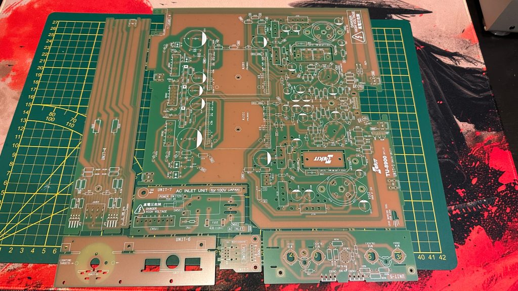
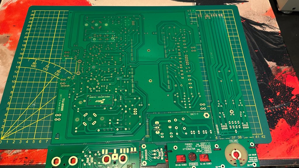
Both sides of the large PCB before snapping it apart.
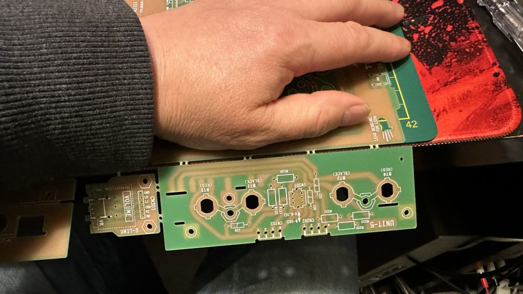
Snapping off one of the PCB boards.
Note that in the center of the large PCB, there are two small boards that also need to be snapped off. One of them — the one with the ELEKIT logo — can be turned into a keychain later if you want 🙂 The other one will be used to mount the input jacks. The holes left behind after snapping them out are meant for bigger coupling capacitors than the ones included in the kit. If you ever want to swap them out for larger ones, that’s where you’ll be able to fit them.
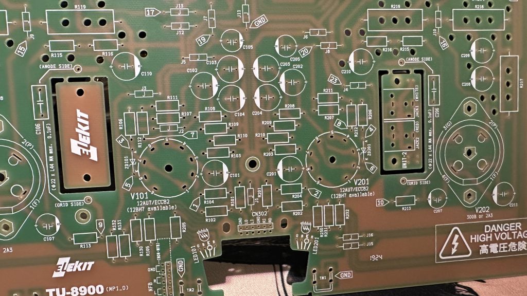
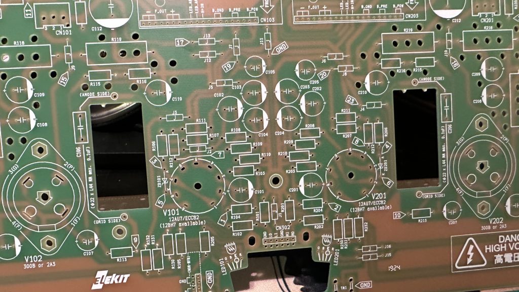
Small breakout boards in the center of UNIT-1 to be snapped off.
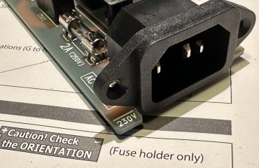
One of the boards, labeled UNIT-7, won’t be used after snapping it off. It’s meant for countries with 100V power supply (like Japan). In the box, you’ll also find a small bag with two similar UNIT-7 boards—one for 110V and one for 230V. We’ll be using the 230V one during assembly. Make sure to pay close attention to this, because if you use the wrong board for your local voltage, the amplifier could be seriously damaged—and it could also be dangerous for you.
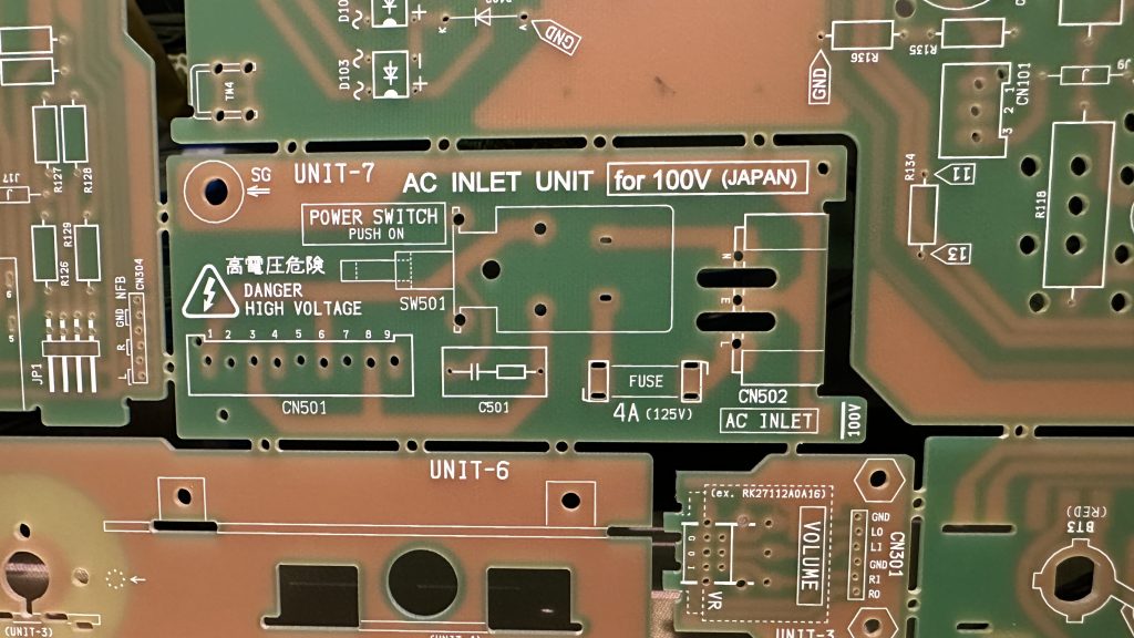
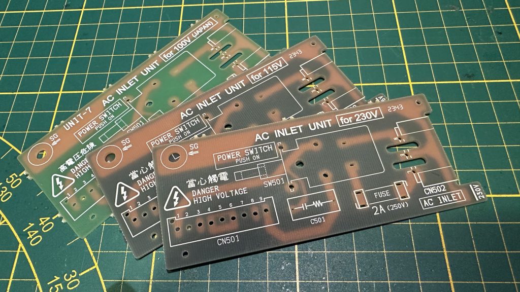
Power supply boards designed for different voltages.
In the bag with the power supply boards, you’ll also find a small plastic tube rolled up from a bag—don’t throw it away! Inside are fuses rated for 250V, which you’ll need. You’ll only use one of them; the other is a spare.
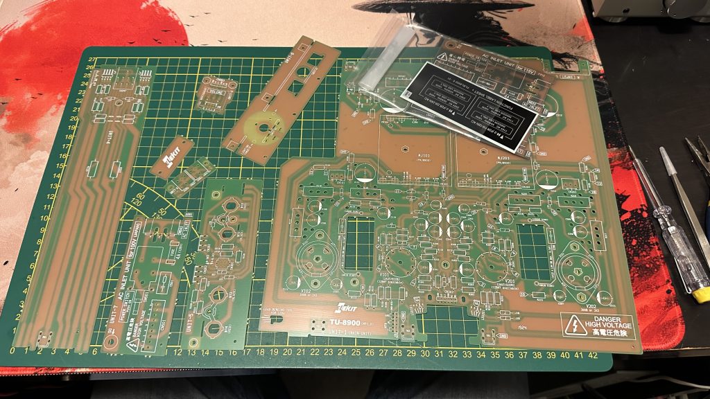
The full set of individual PCB boards after separating them from the main board.
All the other components are packed in two large plastic bags. After opening them, you’ll find smaller bags inside, along with some loose parts.
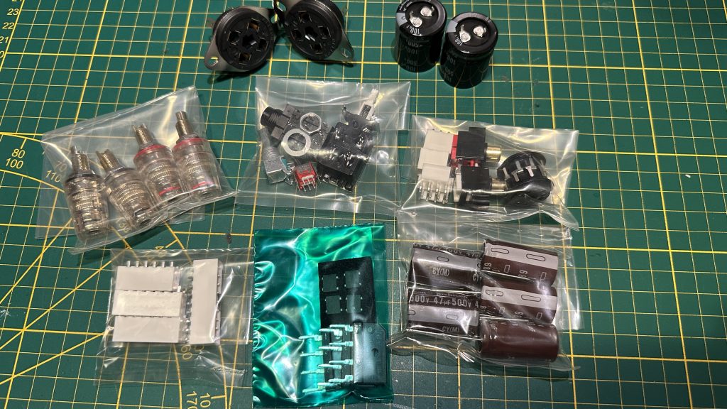
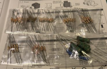
Contents of one of the component bags.
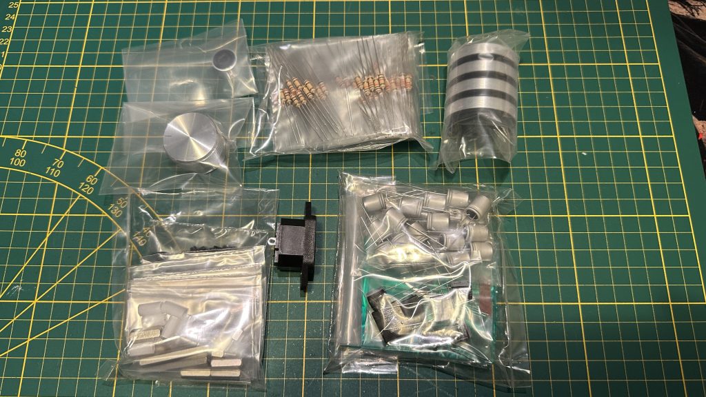
Contents of the second component bag.
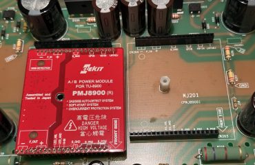
In the box, you’ll also find two pre-assembled PCB boards wrapped in bubble wrap—each in its own separate wrap. These are the boards with the A/B Power Module circuit, responsible for detecting the type of power tube used (2A3 or 300B). The boards are already assembled because all the components used are SMD, which aren’t ideal for amateur work. These components are pretty small, making soldering them quite tricky. That’s why the kit manufacturer decided to have these modules assembled and tested in the factory. During one of the assembly steps, we’ll attach these modules to the amplifier’s main board using connectors, but for now, we can set them aside.
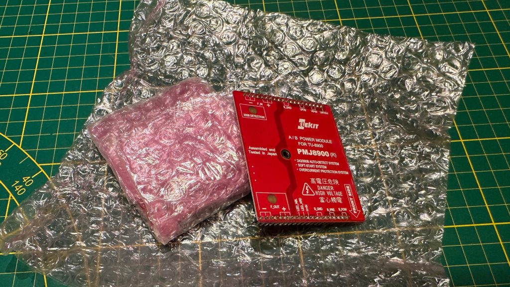
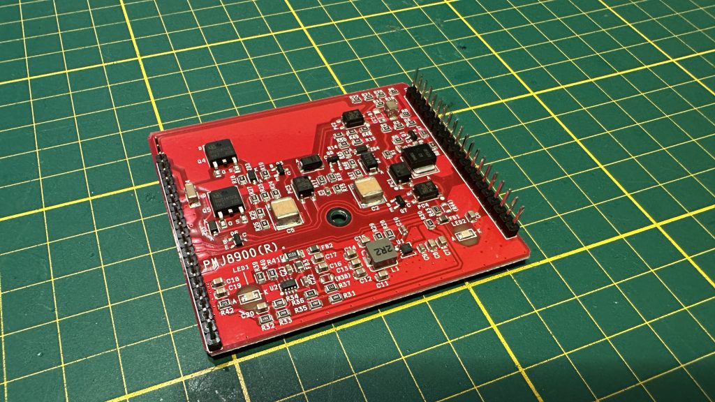
A/B Power Module boards
The kit includes a printed English instruction manual. We highly recommend reading through it and following its guidelines. It’s really clear and well-prepared. It contains lots of diagrams, detailed descriptions, and precise step-by-step instructions for the entire assembly process. Plus, it has plenty of interesting information about tubes and future upgrade options for the amplifier.
At the beginning of the manual, there’s also information about the necessary and useful tools, as well as the types of tubes you’ll need. If you bought the kit with the tubes, there’s no issue. If you got it without the tubes, this section will tell you which ones you can use. For this particular amplifier, you’ll need two power tubes – either 300B or 2A3 – and two ECC82 tubes (the American designation is 12AU7) or 12BH7A (which don’t have a European designation).
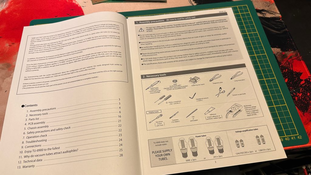
Assembly manual
If you want, before you start the assembly, you can check if all the necessary components are included by using the detailed parts list.
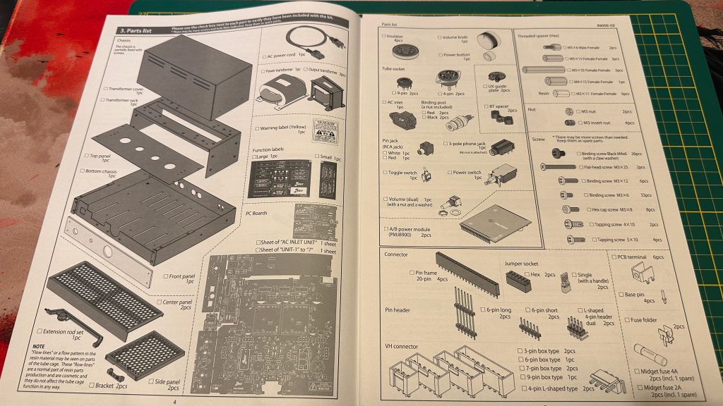
List of all components.
The manual also includes helpful tips worth reading, like the one below, which explains how to remove components (in this case, resistors) from the strip they are glued to. As shown, you shouldn’t pull them out forcefully, as this could damage them, but rather cut them off the strip with pliers.
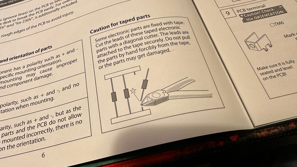
Tips and suggestions – read them, they might come in handy.
Each step is carefully described and illustrated, highlighting important details. Every component also has a special empty checkbox in the description – once you’ve installed a component, you can mark it with a cross. This is an extra way to check the accuracy of your assembly, ensuring you don’t miss any components.
Let’s turn on the soldering iron!
It’s about time to get to the fun part! Let’s start the assembly according to the instructions, beginning with module 2 (UNIT-2). Remember one of those small boards snapped off from the middle of the large one? Well, one of them is exactly what we need right now.
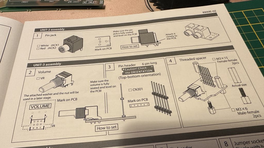
Assembly instructions for UNIT-2.
We’ve got the board, so now let’s take a look at the instructions for the tasks we need to complete. I’m serious – read and understand what’s in the manual. If you need to, dry-fit the components to the board without soldering first. Only grab the soldering iron once you’re sure you know exactly what needs to be done.
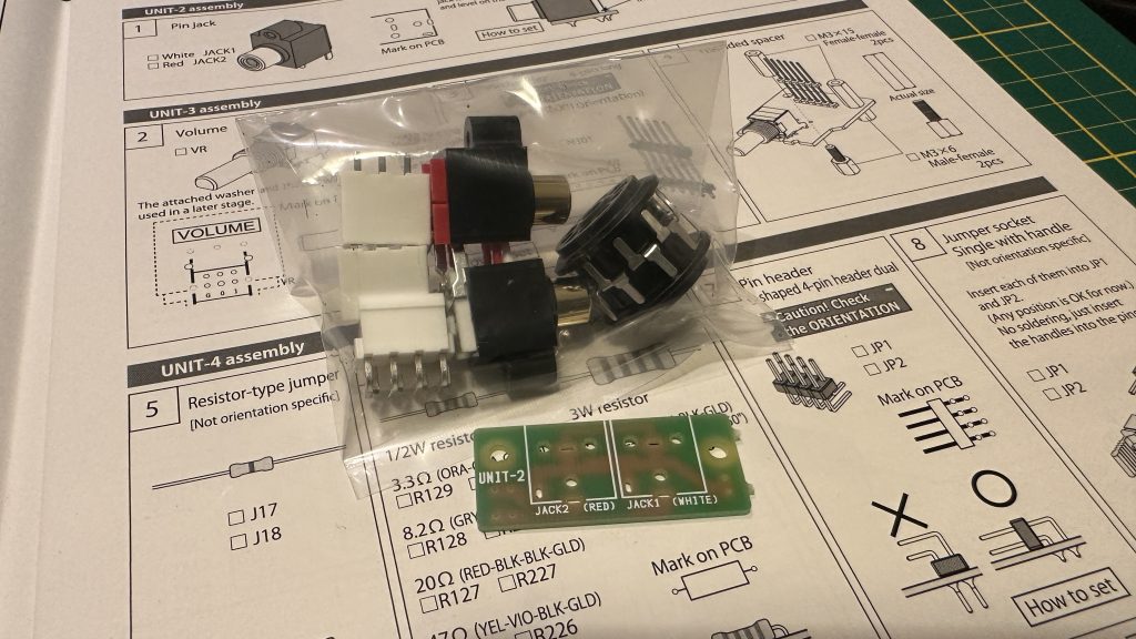
Complete set of components for assembling UNIT-2.
Find the bag with the jack sockets among the components and take them out. Fit them onto the UNIT-2 board and push them into the appropriate holes. Pay attention to the color markings on the board, and note that the sockets might be a bit difficult to insert—they need to be pushed in with all the pins at the same time, along with the plastic guides. The sockets must sit completely flat against the board so they’ll fit properly into the holes in the enclosure later on.
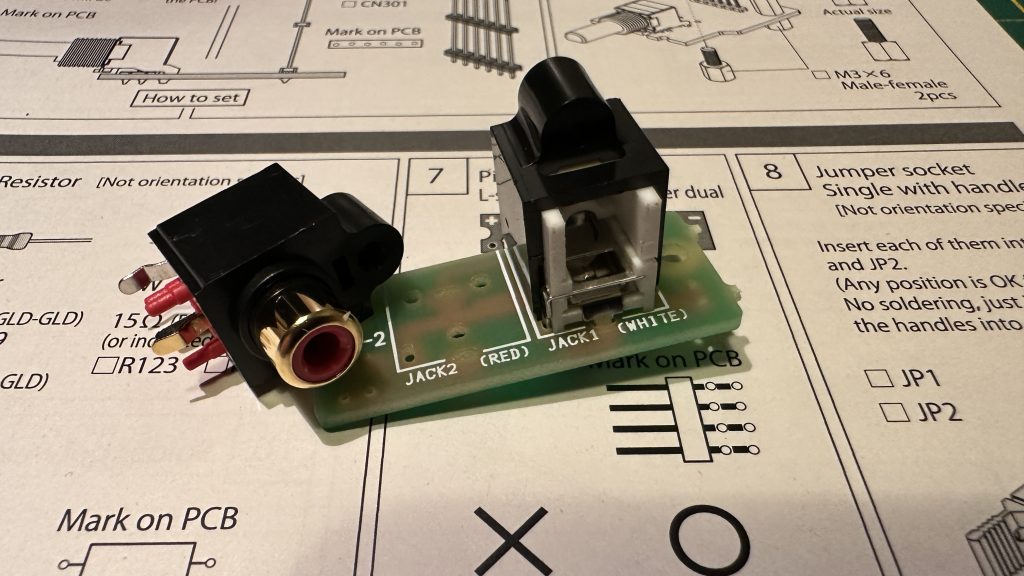
Assembly of the input jacks.
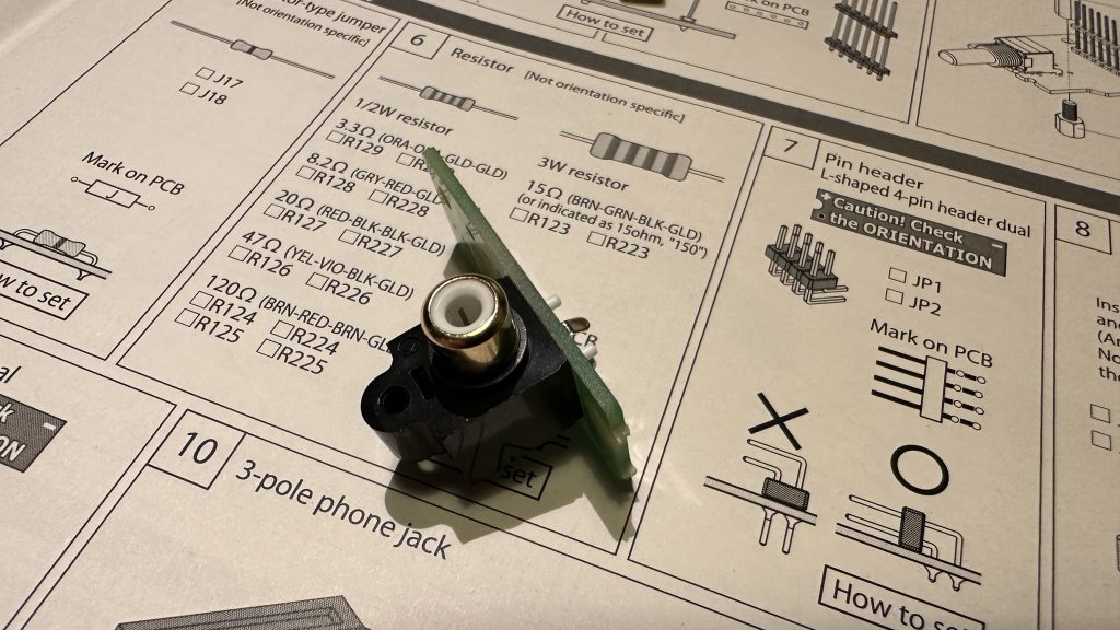
The jack housing must sit flat against the PCB.
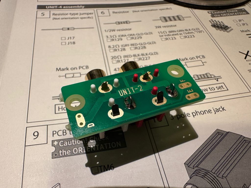
Solder one pin first and then check if the jack is still properly aligned.
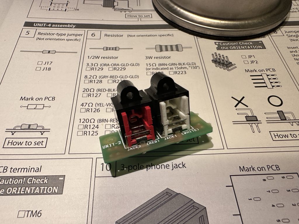
Mounted input jacks.
After inserting the jacks into their respective spots, flip the board over and solder the pins. It’s a good idea to first solder one of the three pins for each jack and check again if it’s pressed properly against the board. If not, you can still fix it—press the board against the jack’s housing and heat up the already soldered pin. Once the solder softens, the board will move slightly towards the jack’s housing, and after cooling, it will securely hold the jack in place. Repeat the process for the second jack, and if everything looks good, solder the remaining pins. Mark in the manual that both jacks are mounted, and we can set the nearly completed UNIT-2 aside for now.
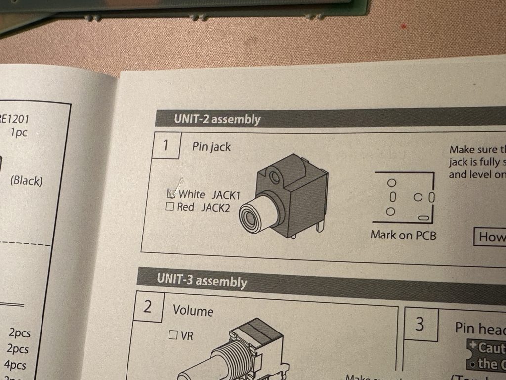
Remember to mark the installation square of each component.
The next board on the list is UNIT-3, which is the volume potentiometer board. Read the instructions and find the components listed. In addition to the potentiometer and the goldpin header, we also need to find the metal spacers. To identify them, you can refer to the 1:1 drawings, like the one in the picture below.
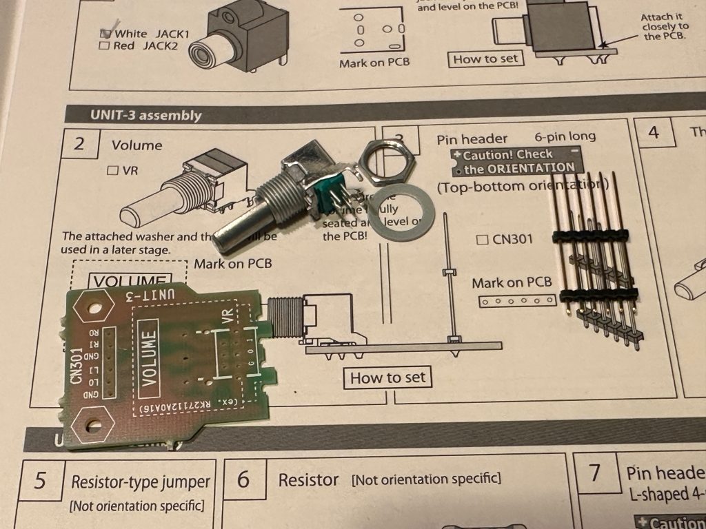
Components for assembly on the UNIT-3 board.
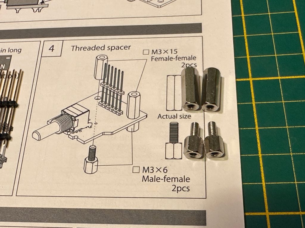
Spacer bushings.
Next, insert the potentiometer into its place. This is similar to the situation with the jacks – it needs to be pressed as close as possible to the PCB. And just like with the jacks, first solder one pin and check if the potentiometer is properly aligned, making adjustments if necessary.
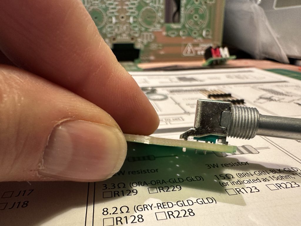
Check if the potentiometer is sitting flush against the PCB.
We can solder the first pin roughly—it only needs to hold the potentiometer in place. Once you’re sure it’s properly positioned, solder the remaining pins and rework the first solder joint if needed.
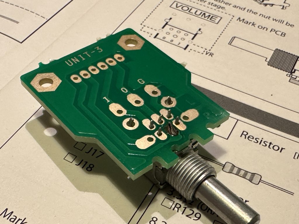
Solder the first pin and then check if the potentiometer is properly inserted.
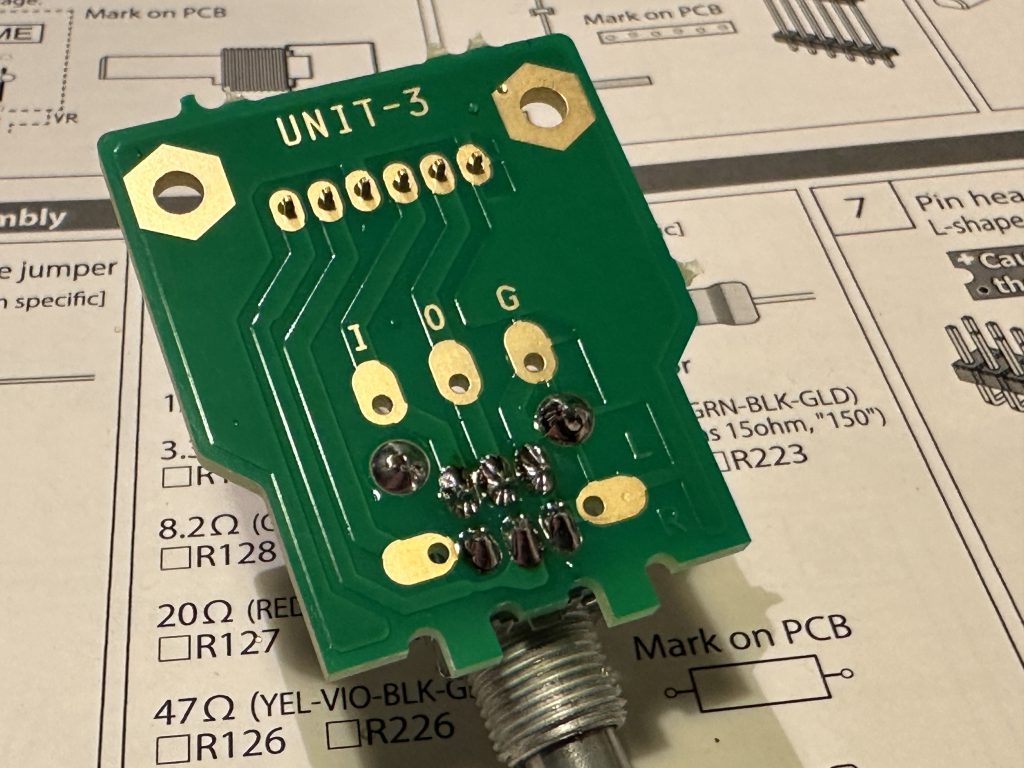
All the potentiometer pins soldered.
The next component is the goldpin header. Insert it into the holes according to the diagram and solder it from the other side. Here’s a small tip—if you’re right-handed, it’s easiest to start soldering a row of pins from the far left. Place the tip of the soldering iron to the right side, and feed the solder from the left. Solder one pin, then move on to the next one. If you solder from the other direction, the iron tip on the right side of the pin might touch the previously soldered one, causing a short. Soldering from the left allows you to see better. After soldering the entire row, hold the board up to the light. If any pins have shorted together, you’ll spot it right away.
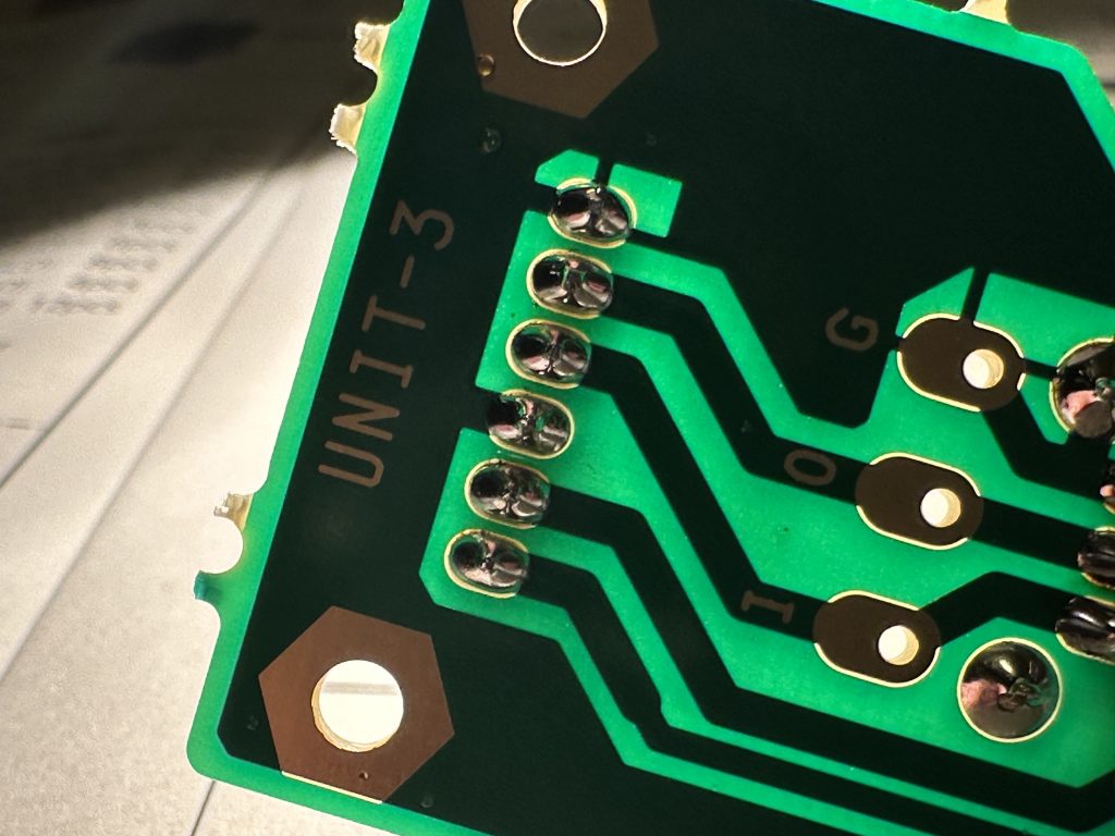
Holding the board up to the light makes it easy to spot any shorts.
The final step is to screw in the spacer bushings. They should be tightened firmly, but not by hand—use pliers or a wrench. Just be careful not to overtighten, as you don’t want to damage the board. Finally, place the washer and nut on the potentiometer’s thread, but don’t tighten them. The goal is just to keep them from getting lost. 🙂
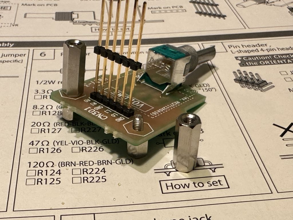
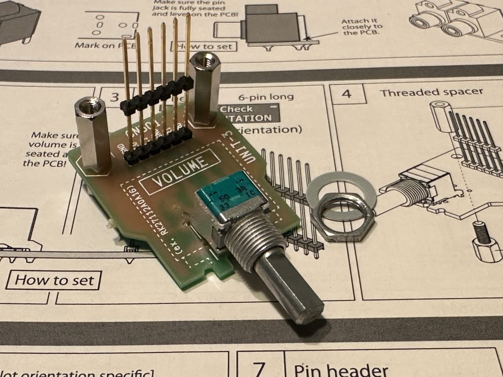
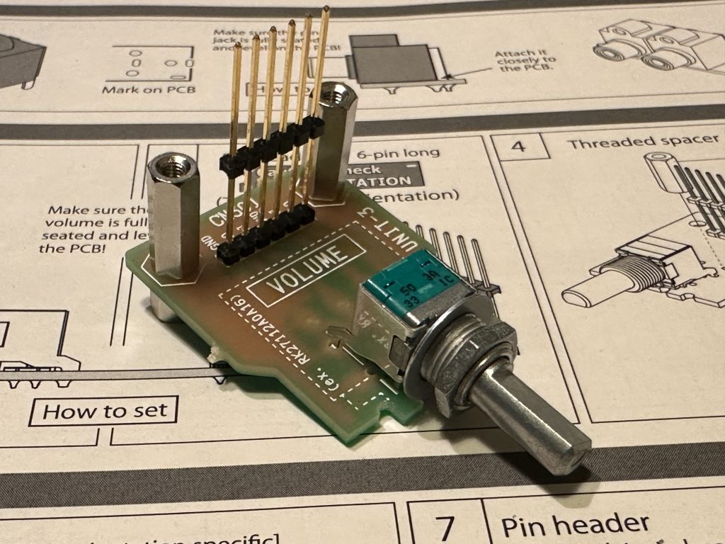
Assembly of the volume potentiometer module.
The completed module is set aside, and we move on to the next step. But that’s for the next part.

You must be logged in to post a comment.